B-31
Cisco IE 3000 Switch Hardware Installation Guide
OL-13017-01
Appendix B Installation In a Hazardous Environment
Installing the Switch
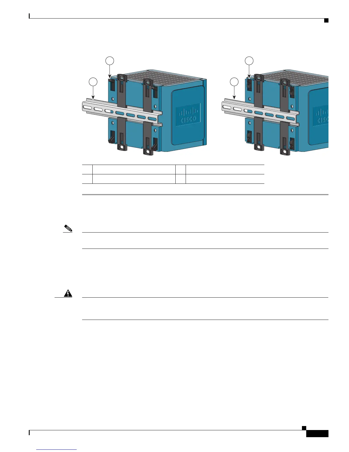
Figure B-22 Mounting the Switch on a DIN Rail in a Parallel Position
After the switch is mounted on the DIN rail, connect the power and alarm wires, as described in the
“Connecting Power and Alarm Circuits” section on page B-36.
Note For instructions on how to remove the switch from a DIN rail, see the “Removing the Switch from a DIN
Rail or a Rack” section on page B-35.
Installing the Switch on a Wall
To attach the switch to a wall or a panel, follow these steps.
Warning
Read the wall-mounting instructions carefully before beginning installation. Failure to use the
correct hardware or to follow the correct procedures could result in a hazardous situation to people
and damage to the system.
Statement 378
1 15-mm DIN rail 3 7.5-mm DIN rail
2 Foot in extended position 4 Foot in recessed position
1 3
2 4
 Loading...