B-33
Cisco IE 3000 Switch Hardware Installation Guide
OL-13017-01
Appendix B Installation In a Hazardous Environment
Installing the Switch
Step 2 Rotate all feet to the recessed positions so that the switch can mount flat on the wall or panel. See
Figure B-22.
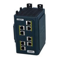
Step 3 Position the rear panel of the switch against the wall or a panel in the desired location. See Figure B-24.
Figure B-24 Mounting the Switch on the Wall
Step 4 Place a number-10 screw that you provide through each DIN rail latch, and screw them into the wall.
After the switch is mounted on the wall or panel, connect the power and alarm wires, as described in the
“Connecting Power and Alarm Circuits” section on page B-36.
Installing the Switch in a Rack
You can use an optional DIN rail adapter kit (available through Cisco, part number
STK-RACKMNT-2955=) to mount the switch in a 19-inch rack. The rack-mounting kit comes with a
DIN rail adapter and screws to attach the adapter to the rack. Ask your Cisco representative for details.
1 Wall
201833
1
 Loading...