B-51
Cisco IE 3000 Switch Hardware Installation Guide
OL-13017-01
Appendix B Installation In a Hazardous Environment
Connecting the Switch to the Power Converter
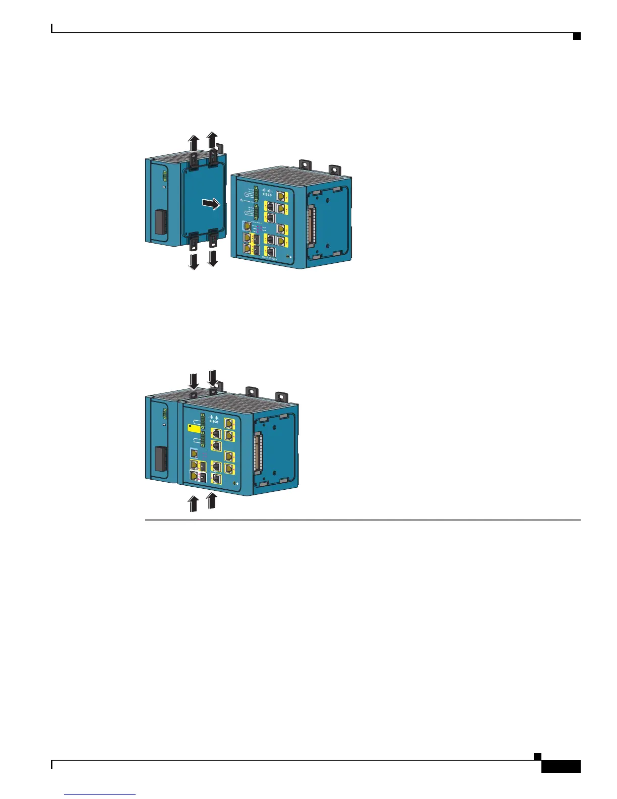
Step 2 Push the upper modules latches (at the top of the switch and the power converter) up and the lower
module latches (at the bottom of the switch and the power converter) down. See
Figure B-39.
Figure B-39 Pushing the Module Latches Up and Positioning the Hardware
Step 3 Put the two modules together so that the power module fits in the switch recess.
Step 4 Push the upper module latches down and the lower module latches up to secure the power converter to
the switch. See
Figure B-40.
Figure B-40 Pushing the Latches In
202296
Cisco
Cat
alyst
Pwr A (24VDC or 48 VDC)
Rtn A
Pwr B (24VDC or 48 VDC)
Rtn B
Express Setup
System
Alarm
Setup
Pwr A
Pwr B
Major Alarm
Minor Alarm
Th
i
s
u
nit m
i
g
h
t
h
ave mo
re
than
one
p
ow
er co
r
d. T
o
redu
c
e
t
he
risk of
e
le
ctric sh
o
ck
d
is
co
n
ne
c
t th
e
tw
o
p
ow
e
r cord
s
be
f
o
re
s
e
rvicing un
it
.
WARNING
!
202297
1
5
2
6
3
7
4
8
CONSOLE
1
2
 Loading...