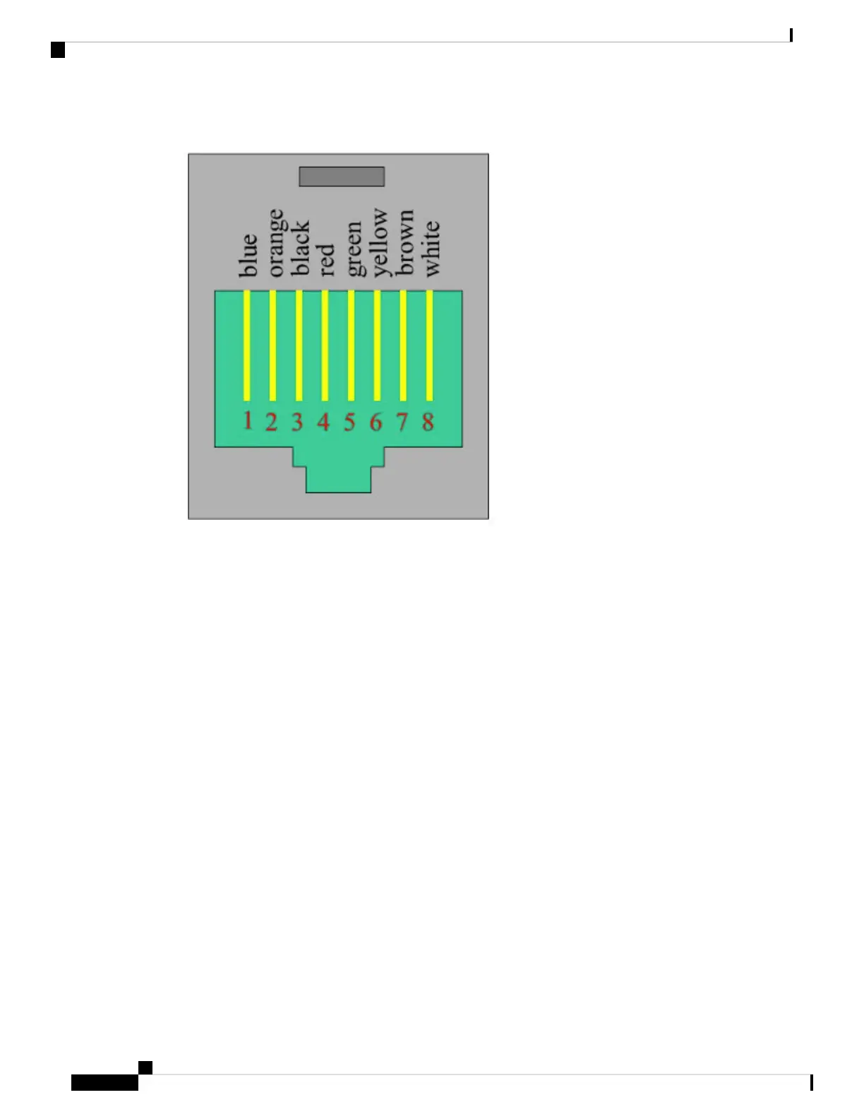
Figure 46: RJ-45 Female Pinouts
Now that both sides of the adapter have been explained, the next step is to place the pins into the proper holes
of the DB9 side of the connector. This is done with the use of a pinning tool. An example of a common pinning
tool is found in Figure 47: Pinning Tool, on page 73.
IR1101 Industrial Integrated Services Router Hardware Installation Guide
72
Connecting the Router
RJ-45 Adapter Side
 Loading...