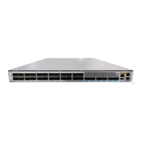
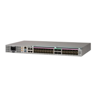
GNSS Module (A900-CM-GNSS)
The GNSS module is present on the RSP. It is a pluggable module that allows direct interface with the external
antenna.
Using a single GPS antenna input for both RSPs requires usage of external splitters.
Note
To reduce the risk of fire, use only No. 26 AWG or larger telecommunication line cord. Statement 1023
Warning
The GNSS module is not hot swappable.
Note
GNSS Module RF Input Requirements
• The GNSS module requires an active GPS/GNSS antenna with built-in Low-Noise Amplifier (LNA) for
optimal performance. The antenna LNA amplifies the received satellite signals for two purposes:
• Compensation of losses on the cable
• Lifting the signal amplitude in the suitable range for the receiver frontend
The Amplification required is 22dB gain + cable/connector loss + Splitter signal loss.
The recommended range of LNA gain (LNA gain minus all cable and connector losses) at the connector
of the receiver module is 22dB to 30dB with a minimum of 20dB and a maximum of 35dB.
• GNSS module provides 5V to the active antenna through the same RF input.
• Surge requirement:
• GNSS modules have built-in ESD protections on all pins, including the RF-input pin. However,
additional surge protection may be required if rooftop antennas are being connected, to meet the
regulations and standards for lightning protection in the countries where the end-product is installed.
• A lightning protection must be mounted at the place where the antenna cable enters the building.
The primary lightning protection must be capable of conducting all potentially dangerous electrical
energy to PE (Protective Earth).
• Surge arrestors should support DC-pass and suitable for the GPS frequency range (1.575GHz) with
low attenuation.
• Antenna Sky visibility:
The antenna terminal should be earthed at the building entrance in accordance
with the ANSI/NFPA 70, the National Electrical Code (NEC), in particular Section
820.93, Grounding of Outer Conductive Shield of a Coaxial Cable.
Note
Cisco NCS 560-4 Router Hardware Installation Guide
8
Cisco NCS 560-4 Router Overview
GNSS Module (A900-CM-GNSS)
 Loading...
