Installing an Interface Module
Procedure
Step 1 Slip on the ESD-preventive wrist strap that was included in the accessory kit.
Step 2 Before inserting an interface module (IM), make sure that the chassis is grounded.
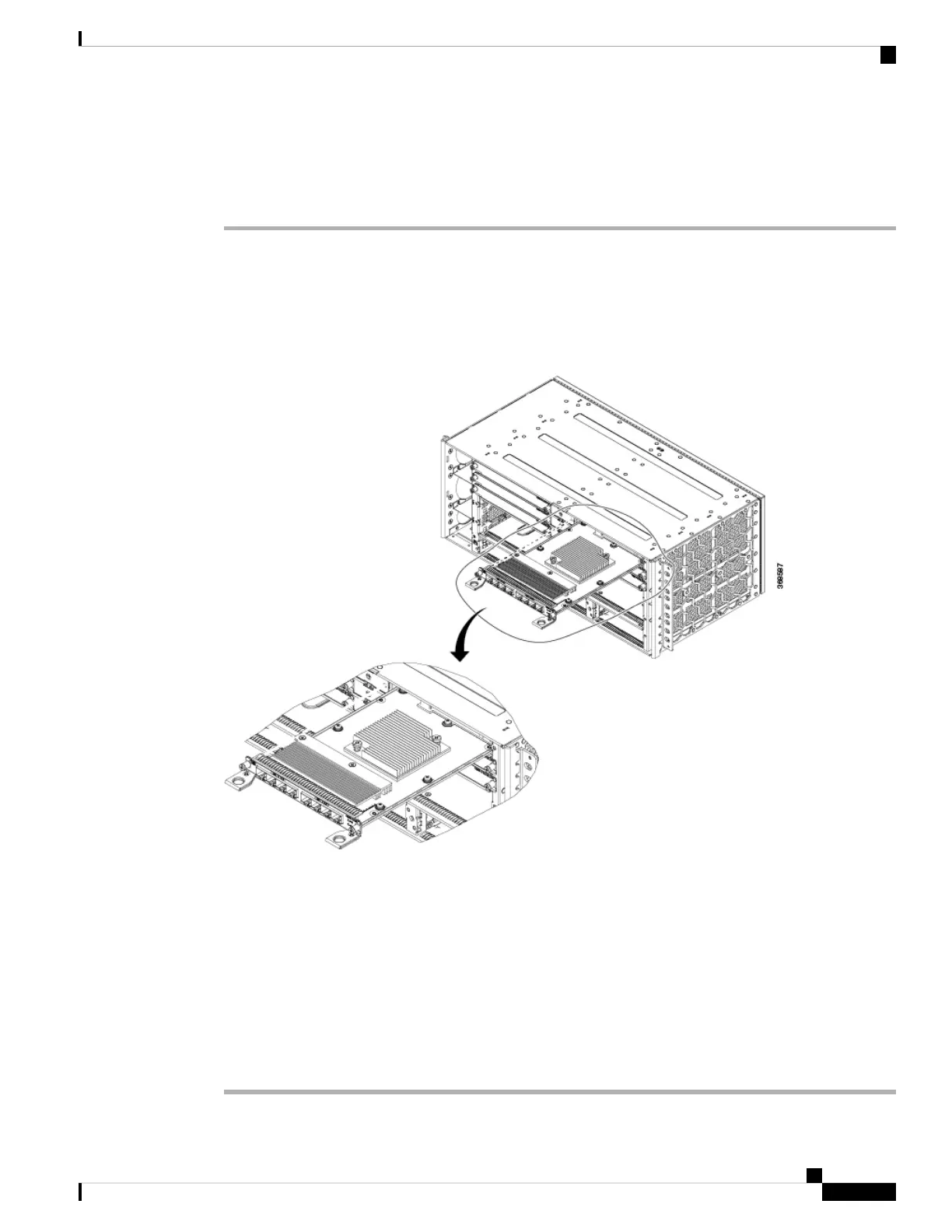
Step 3 To insert the IM, carefully align the edges of the IM between the upper and lower edges of the IM slot.
Step 4 Carefully slide the IM into the slot until the IM makes contact with the backplane.
Figure 45: Inserting an Interface Module
Step 5 Tighten the locking thumbscrews on both sides of the interface module. The recommended maximum torque
is 5.5 in.-lb (.62 N-m).
Step 6 Connect all the cables to each interface module when ready for test and turn-up.
Do not use interface module and power supply ejector handles to lift the chassis; using the handles
to lift the chassis can deform or damage the handles
Caution
Close all unused RJ-45, SFP, XFP, and QSFP ports on the interface module using the appropriate
dust caps to prevent dust from accumulating inside the cage. For information on dust caps, see
Installing Dust Caps .
Note
Cisco NCS 560-4 Router Hardware Installation Guide
87
Installing the Cisco NCS 560-4 Router
Installing an Interface Module