Internal Components
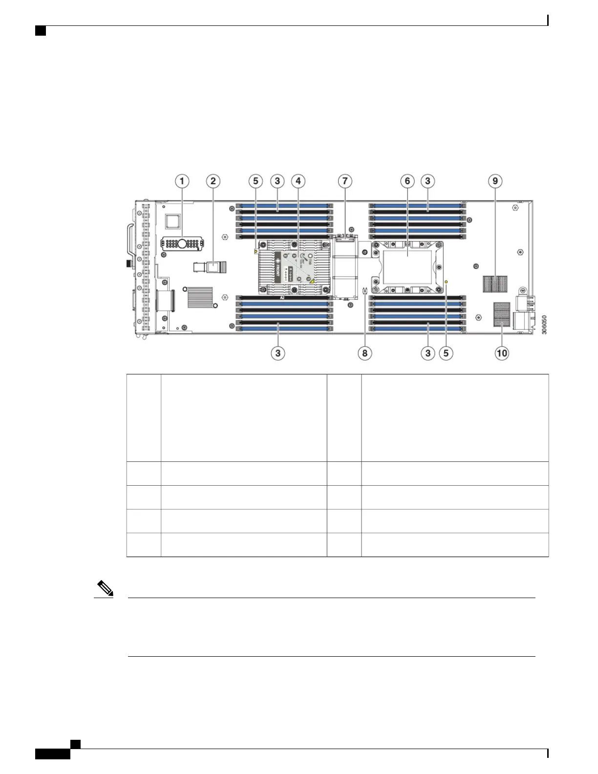
The following figure shows the internal components of the Cisco UCS B200 M5 blade server.
Figure 5: Inside View of the Cisco UCS B200 M5 Blade Server
USB connector (populated)
An internal USB 3.0 port is supported. A 16
GB USB drive (UCS-USBFLSHB-16GB) is
available from Cisco. A clearance of 0.950
inches (24.1 mm) is required for the USB
device to be inserted and removed.
2Front mezzanine connector1
CPU 1 socket (populated)4DIMM slots3
CPU 2 socket6CPU heat sink install guide pins5
Diagnostic button8Mini storage connector7
Rear mezzanine connector10mLOM connector9
When the front mezzanine storage module is installed, the USB connector is underneath it. Use the small
cutout opening in the storage module to visually determine the location of the USB connector when you
need to insert a USB drive. When the NVIDIA GPU is installed in the front mezzanine slot, you cannot
see the USB connector.
Note
Cisco UCS B200 M5 Blade Server Installation and Service Note
14
Servicing a Blade Server
Internal Components

 Loading...