Procedure
Step 1
Using a #1 Phillips-head screwdriver, loosen the screw securing the M.2 card to the top of the M.2 mini-storage
module.
Step 2
Pull the M.2 card from the module connector.
Step 3
Repeat these steps to remove the M.2 card from the bottom of the M.2 mini-storage module.
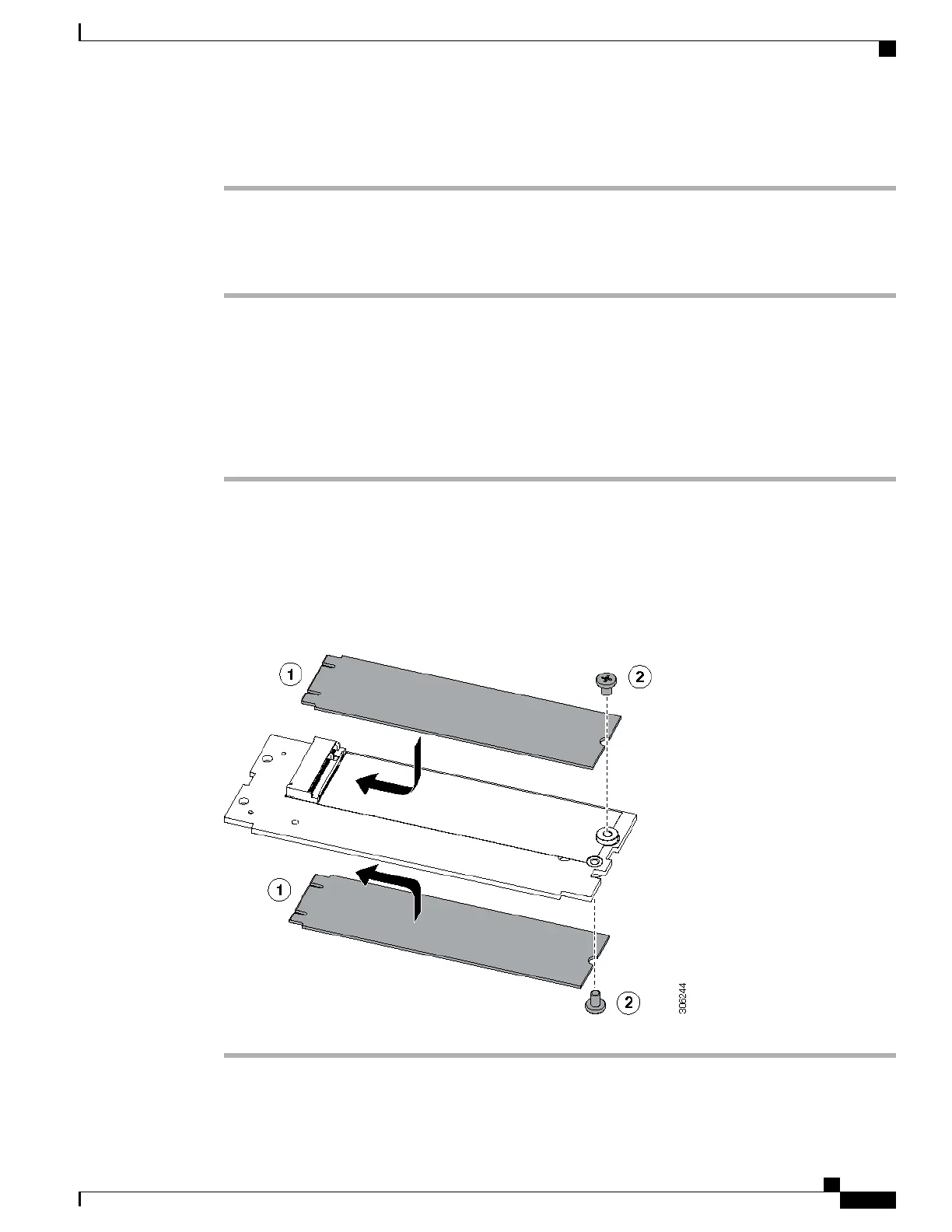
Installing the SATA 3.0 M.2 Cards
This task describes how to install the SATA 3.0 M.2 cards into the M.2 mini-storage module.
Procedure
Step 1
Align the gold fingers on the M.2 card with the module connector on the top of the M.2 mini-storage module,
and then fully push the M.2 card into the module connector.
Step 2
Using a #1 Phillips-head screwdriver, tighten the provided screw to secure the M.2 card to the M.2 mini-storage
module.
Step 3
Repeat these steps to install the M.2 card on the bottom of the M.2 mini-storage module.
Figure 9: Installing the SATA 3.0 M.2 Cards
Cisco UCS B200 M5 Blade Server Installation and Service Note
27
Servicing a Blade Server
Installing the SATA 3.0 M.2 Cards