EasyManuals Logo

Cisco UCS B200 M5 User Manual

Cisco UCS B200 M5
74 pages
To Next Page IconTo Next Page
To Previous Page IconTo Previous Page
Page #36 background imageLoading...
Page #36 background image
Procedure
Step 1
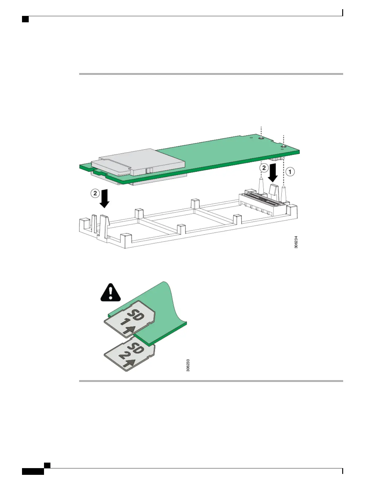
Align the two holes on the module with the holder pins.
Step 2
Push the module into the holder on both ends, making sure the holder clips snap in. Push on the four corners
of the module to fully install it. Avoid touching board components.
Figure 8: Installing the Mini-Storage Module
Note the orientation of the SD cards. They should be inserted with the label facing
up.
Note
Removing the SATA 3.0 M.2 Cards
This task describes how to remove the SATA 3.0 M.2 cards from the M.2 mini-storage module.
Cisco UCS B200 M5 Blade Server Installation and Service Note
26
Servicing a Blade Server
Removing the SATA 3.0 M.2 Cards

Table of Contents

Questions and Answers:

Question and Answer IconNeed help?

Do you have a question about the Cisco UCS B200 M5 and is the answer not in the manual?

Cisco UCS B200 M5 Specifications

General IconGeneral
Form FactorBlade
ProcessorIntel Xeon Scalable Processors
ManagementCisco UCS Manager
Processor Sockets2
Product TypeBlade Server
MemoryUp to 3 TB DDR4
Memory Slots24 DIMM slots
StorageUp to 2 x SAS/SATA drives
Expansion SlotsMezzanine card
RAID SupportRAID 0, 1
Network10 Gigabit Ethernet, 25 Gigabit Ethernet
Power SupplyPart of UCS Blade Server Chassis

Related product manuals