Procedure
Step 1
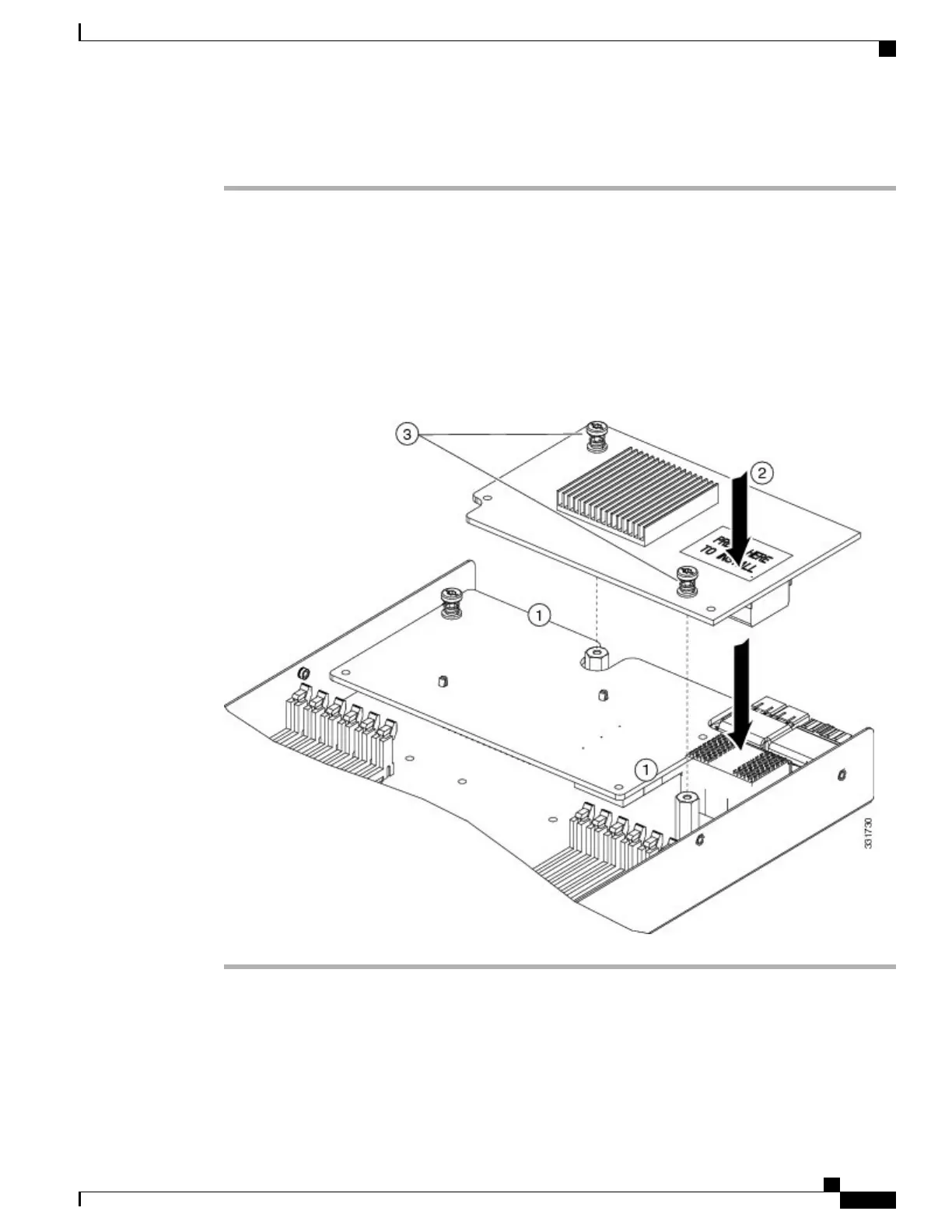
Position the rear mezzanine module above the motherboard connector (callout 1) and align the two rear
mezzanine module captive screws to the standoff posts on the motherboard.
Step 2
Firmly press the rear mezzanine module into the motherboard connector (callout 2) where “PRESS HERE
TO INSTALL” is stated.
Step 3
Tighten the two rear mezzanine module captive screws (callout 3).
Removing a rear mezzanine module is the reverse of installing it. You might find it helpful when
removing the rear mezzanine module from the motherboard to gently rock the rear mezzanine module
along the length of the motherboard connector until it loosens.
Tip
Figure 18: Installing a Rear Mezzanine Module
Cisco UCS B200 M5 Blade Server Installation and Service Note
41
Servicing a Blade Server
Installing a Rear Mezzanine Module in Addition to the mLOM VIC

 Loading...