77
Operating Manual
1
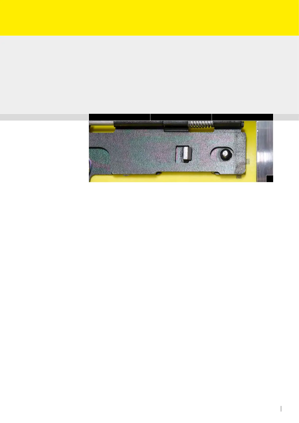
Positioning correction
The position of the grid sheet form can be changed laterally, circumferentially as well as
transversally on the base plate (± 1,5 mm).
• First loosen the at head screws on the rear locking hinge, then loosen the corre-
sponding at head screws on the front locking hinge and reposition to suit (Fig. 1).
• Re-tighten the at head screws on the front locking hinge. Tension the grid sheet on
the rear locking hinge with the aid of the unlocking tool and re-tighten the at head
screws.
 Loading...