Model FLE Assembly Casing Assembly
750-192 3-11
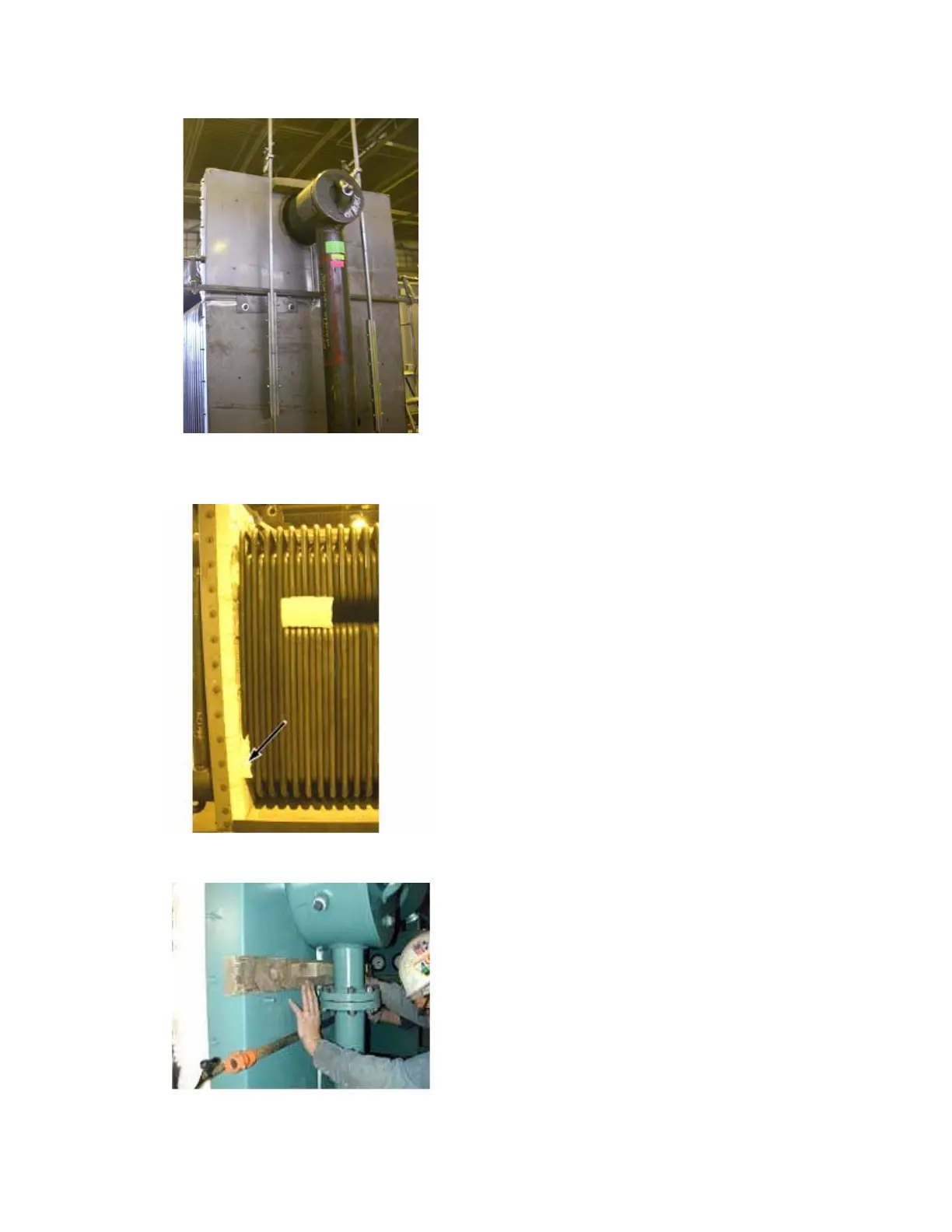
Figure 3-15. Use bar clamps and wedges to align
wall
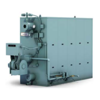
Figure 3-16. Insulation in the gaps
Figure 3-17. Use bar clamps and wedges to align
wall
4. With bar clamps, clamp the walls together at the cor-
ners of the wall and clamp the entire wall to the base
of the boiler (Figure 3-15).
5. Make sure that the walls are flush with each other
and secure all of the bolts.
6. Remove the clamps.
7. Check that the sides of the wall line up with the base
angles. If not, loosen the bolts and/or nuts on the
bolting plates and move the wall. If the wall will not
line up exactly, then center the wall in relation to the
base angles. Tighten the nuts and bolts on the bolt-
ing plates to secure the walls to the base.
8. Attempt to slide a box cutter into all of the seams
where insulation is visible. If the knife is able to
enter, then gasses can escape. Tighten the bolts and
repeat the last three steps.
9. Trim all of the visible insulation from the joints.
10. If necessary, use the wedge described earlier, to
make the wall stand upright.
11. Install a pyro-log insulation block (872-911) in the
pass opening near the rear and in the gap left by the
tubes at the bottom (Figure 3-16). The insulation
block should be compressed together slightly and
should be installed flush with the outside of the
tubes. They should be turned vertically to fill in the
turn around area. Trim to fit as necessary.