of 5041
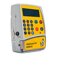
5. Remove the 4 pumping block screws. These screws secure the pumping block
to the front housing.
4 pumping block screws
6. Disconnect the motor connector
on the motor PCB.
7. With the keypad facing up,
observe the two metal hinge support features protruding from the front of the
front housing assembly. Apply pressure evenly to the two hinge support
features to push the motor block assembly out of the front housing assembly.
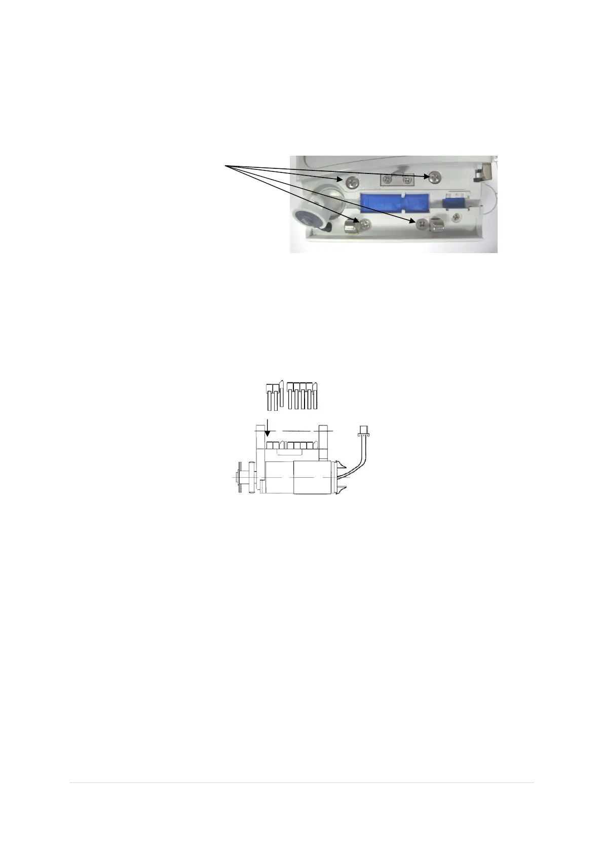
8. Install the old pumping fingers into the new pump block as illustrated below.
Position fingers into slots in the pump block above cam.
Ensure beveled side of fingers face encoder plate.
Position of Pumping Fingers in Pumping Block
9. Replace the motor block assembly by turning the front housing assembly so that
the key pad is facing up.
10. Insert the new motor block assembly through the back side of the front housing
so that the assembly is seated firmly against the inside of the front housing.
11. Reassemble in reverse order.
12. Perform Operational Checklist and Performance Acceptance Test.
3. Replacement of Pressure Sensor
1. Remove the pump door as described above.
2. Remove the pumping block assembly as described above.
3. Remove the 3 screws holding the motor PCB in place, carefully remove
the Motor PCB.
 Loading...