of 5043
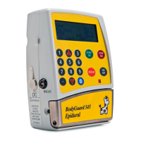
5. Put a few drops of super glue on the
sensor ‘ears’. Keep the ‘Go-No-Go’
gauge in between the sensors to
ensure correct distance until the glue
is dry.
6. Reassemble in reverse order.
7. Perform the Operational Checklist Performance Acceptance Test.
4.2 Door Air Sensor:
1. Separate the front and rear housing.
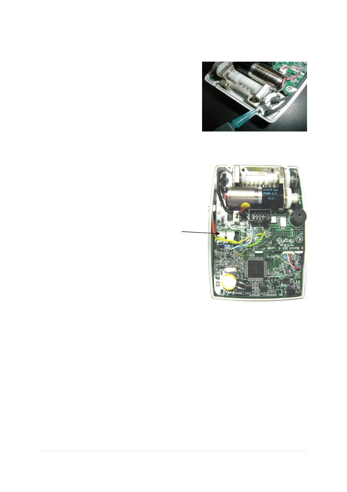
2. Disconnect the door mounted air sensor at
connector JP5.
Door Mounted Air sensor connector JP5
3. Remove the air sensor door screw.
4. Remove the sensor by using a sharp knife to remove the connector pins from
the air sensor connector. Save this connector for later use.
5. Replace the sensor with a new one.
6. Insert the leads of the air sensor through the hole in the front housing.
7. Insert the blue and white lead connector pins into the air sensor connector
housing. Insert pins into the connector housing so that when connected to the
JP5 connector, the blue wire is inserted in the outside position, the white wire
is inserted in the inside position.
8. Check that the distance is 2.3mm between the air sensors using the ‘Go-No-
Go’ gauge and perform the air sensor testing procedure, as described on p. 19.
9. Perform Operational Checklist and Performance Acceptance Test.
 Loading...