of 5042
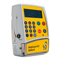
4. Remove the M2 screw from the inside of the pumping chamber located
on the front housing near the pressure sensor.
M2 screw
5. Turn pump over and remove the self
tapping screw holding the pressure sensor in
place.
6. Pull the pressure sensor out of its recess.
7. Install new pressure sensor.
8. Reassemble in the reverse order.
9. Perform Operational Checklist and Performance Acceptance Test.
4. Replacement of Air Sensors
4.1 Front housing mounted air sensor:
1. Separate the front and rear housing.
2. Disconnect the front housing mounted
air sensor at connector JP4 on main PCB.
Front housing mounted
Air sensor connector JP4
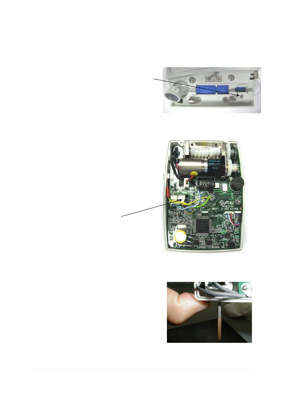
3. The air sensor is glued to the front
housing. Using a screwdriver, apply enough pressure to the ‘ears’ on the back
of the sensor to break them off, and then push the sensor out of its recess.
4. Rep
lace the sensor with a new one.
Use the Go No-Go gauge pins, (2.2
mm GO and 2.3 mm NO-GO) to
ensure that the distance between the
door mounted air sensor and the
onboard air sensor is 2.3 mm.
 Loading...