CNC-STEP e.K. ▪ Siemensstrasse 13-15 ▪ 47608 Geldern ▪ Germany
Support: +49 (0)2831/91021-50
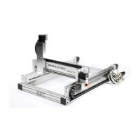
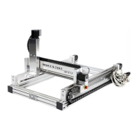
4.3.2 Y- a xis w ith carria g e
Tool holder (43H7 holder)
Fig.12: Y-carriage bellow opened
The two linear guides (Fig. 12/1) and the ball screw (Fig. 12/2)
are located on the Y-bridge (Fig. 11/1) and represent the y-axis.
Along the Y-bridge the tool holder(Fig. 11/2) is moved with
suitable tool(43H7 tool holder).
HINT:
Reference switches are required for axes without absolute position encoder to
feature in the initialization of the axis by a known reference point (zero point of the
axis). From this position, all other positions are then calculated relative to the
process of the axis via software.
 Loading...