ATTENTION:
Risk of tripping and falling!
Exposed wires on the ground can lead to tripping or slipping.
• On the ground laid cables should be covered.
• Do not lead past corners and sharp edges.
• Avoid chafing.
• Visibly mark line course.
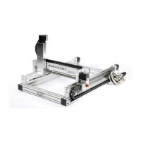
Connect the stepper motor and control cable with the following
assignment to the stepper motor controller:
• The port X (Fig. 27/1) of the junction box connect to
the connector X1 of the stepper motor control.
• The port Y (Fig. 27/2) connect the junction box to the
terminal Y of the stepper motor control.
• Connect the port Z (Fig. 27/3) of the connection box to
the terminal Z of the stepper motor control.
• Control line (emergency stop switch, limit and
reference switches) connect to terminal ST of the
connection-box with the ST connection of stepper
motor control.
 Loading...