MBF-40 SMR700/SMR800 PS REPEATER
PRODUCT DESCRIPTION AND USER’S MANUAL
www.cobham.com/wireless Date: 28-Jan-16 Cobham Wireless – Coverage
Page | 30
Rev. 2.1 Doc. No. 00046UM
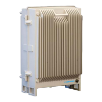
2. Switch on the Power Switch.
3. Switch on the BATT power.
Figure 2-28: Power and Battery Switches
4. Referring to section 5.3, verify the LEDs from the following modules are indicating correct
operation:
• Control module
• F/O converter(s)
• Power supply module(s)
2.3.7.3 About the Backup Battery
• On the Power Supply unit a rechargeable battery pack in mounted. This part also includes
charging and supervision electronics.
• The backup battery will provide the Control Module with enough capacity to send an alarm in
case of input power failure.
• The battery can be switched on and off. The switch is placed adjacent to the main power switch
on the power supply.
• At delivery the back-up battery is connected.
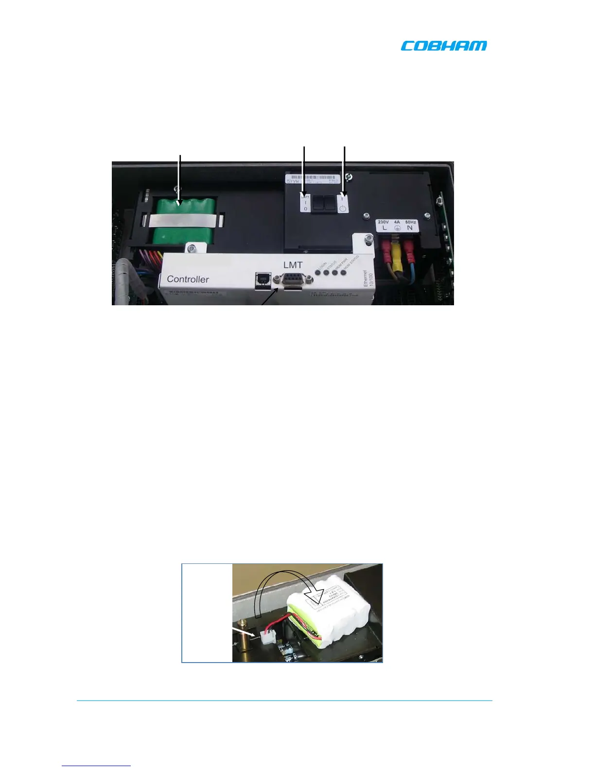
• The battery is replaced by lifting the battery pack out of the crate and disconnecting the cable.
Figure 2-29: Backup Battery