98-175666-D Appendix C: Miscellaneous C-8
Dual modem operation
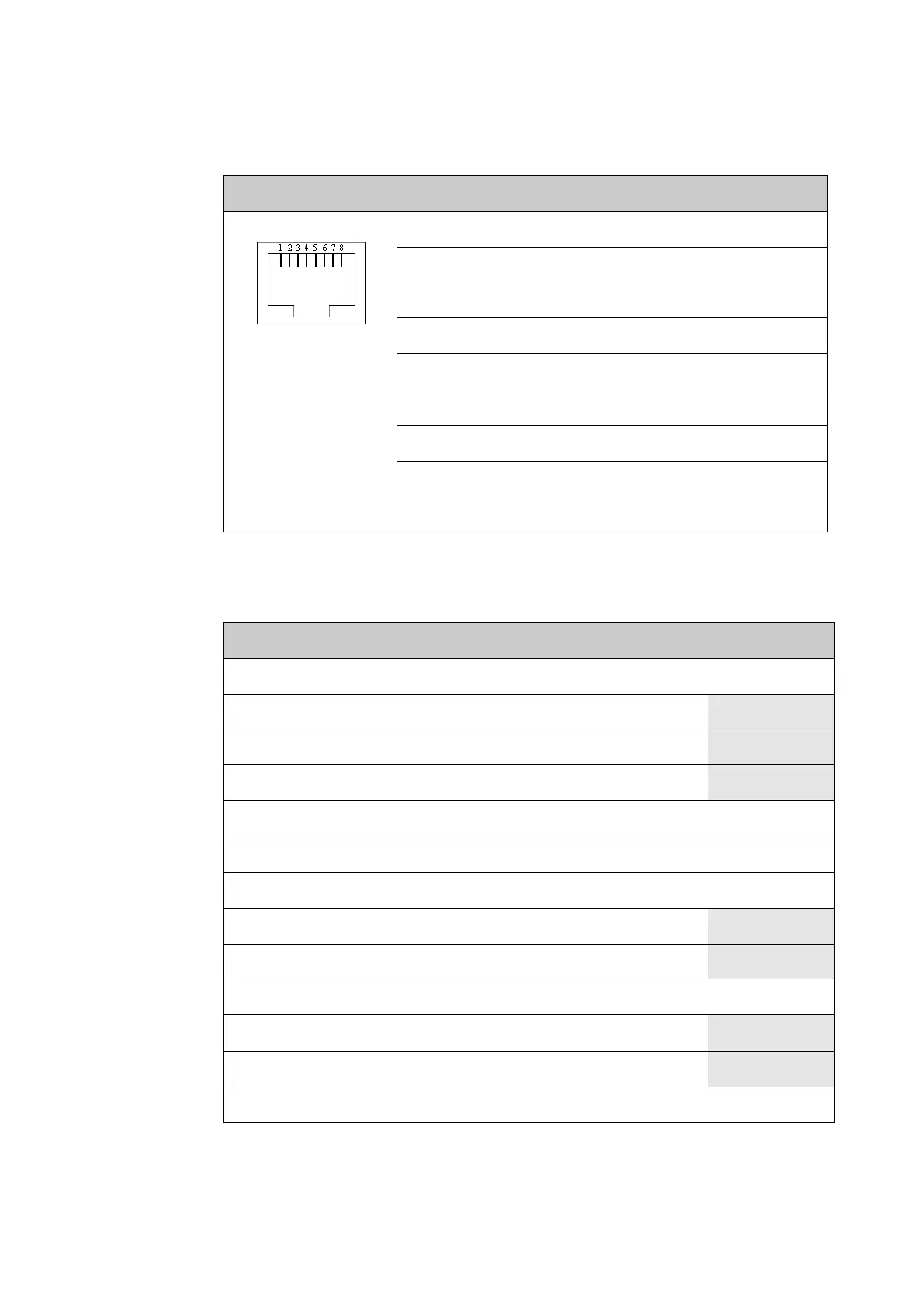
The antenna will detect modem RX Lock if pin 8 (CM RSSI) on RS-232 port is above
1000 mV. See the table below for pinout.
The SLM-5650 modem offers an analogue AGC Monitor test point pin on the J9
Auxiliary connector. See the table below for pinout.
Outline Pin I/O Signal Function
1 I RSSI 2 CM temp out of range
2 I DTR/Rx Lock CM power good
3 I RXD BUC TXD
4 - GND Ground
5 - GND -
6 O TXD BUC RXD
7 I DSR/TX Mute GMU reset
8 I RSSI 1 CM RSSI
Shield - PCB ground PCB ground
Table C-3: RJ-45 RS-232 connector, male, outline and pin assignment
Pin Signal function Name
1 Demod I Channel I
2 Spare
3 Spare
4 Reserved for Redundancy Switch
5 Chassis Ground GND
6 Demod Q Channel Q
7 AGC Monitor Test Point AGC
8 Spare
9 Reserved for Redundancy Switch
10 Ext Carrier Off EXT
11 Reserved for Redundancy Switch
12 Reserved for Redundancy Switch
13 Tx TTL Fault TxFLT
Table C-4: SLM-5650 modem, Auxiliary Connector J9

 Loading...


