98-175666-D Appendix C: Miscellaneous C-9
Dual modem operation
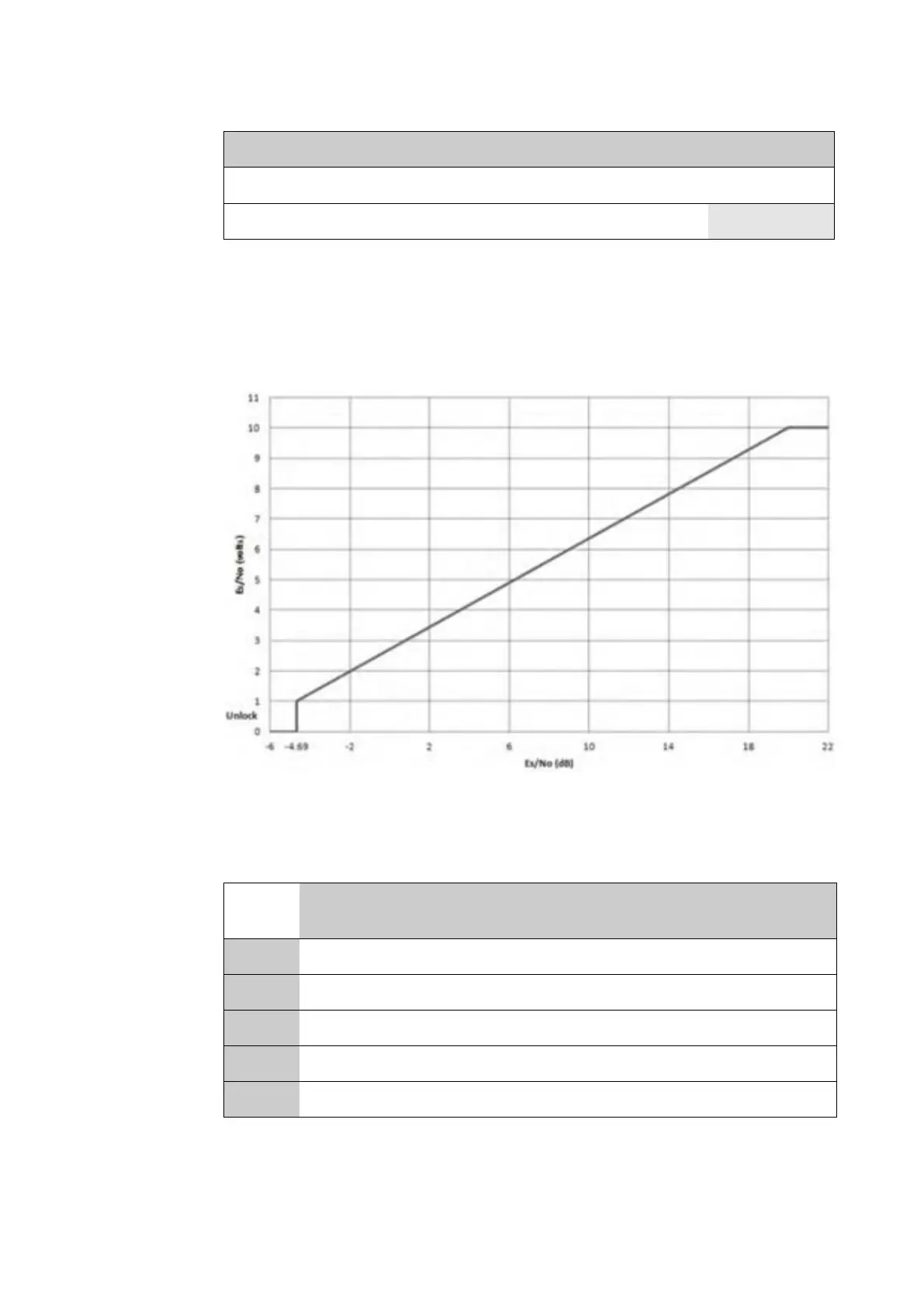
Pin 7 of the auxiliary connector (Table C-4) provides an analogue signal to aid antenna
pointing. The analogue signal will be zero volts when the modem is not locked to a
carrier. When locked to a carrier the analogue signal will be 1 volt for Es/No values less
than or equal to -4.69 dB, or 10 volts for Es/No values greater than or equal to 20dB as
depicted in the following chart.
The SAILOR XTR GX-R2 antenna can transmit from 27.5 GHz to 30.0 GHz in five bands of
500 MHz. It is important that the SLM-5650 Tx frequency is configured to match these
Tx bands. See the table below.
14 Rx TTL Fault RxFLT
15 Reserved for Redundancy Switch
Figure C-3: Modem Rx Lock Level
LO freq. RF Low freq.
RF High
freq.
L-Band Low
freq.
L-Band High
freq.
Band 1 26.55 27.5 GHz 28.0 GHz 950 MHz 1450 MHz
Band 2 27.05 28.0 GHz 28.5 GHz 950 MHz 1450 MHz
Band 3 27.55 28.5 GHz 29.0 GHz 950 MHz 1450 MHz
Band 4 28.05 29.0 GHz 29.5 GHz 950 MHz 1450 MHz
Band 5 28.55 29.5 GHz 30.0 GHz 950 MHz 1450 MHz
Table C-5: Tx bands
Pin Signal function Name
Table C-4: SLM-5650 modem, Auxiliary Connector J9

 Loading...


