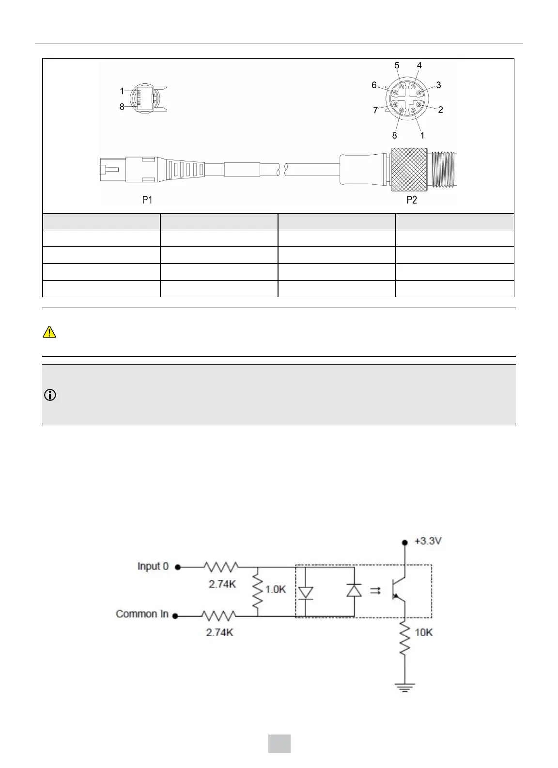
P1 Pin Number Wire Color Signal Name P2 Pin Number
5 White/Blue TxRx C - 7
6 Green TxRx B - 4
7 White/Brown TxRx D + 5
8 Brown TxRx D - 6
CAUTION: The Ethernet cable shield has to be grounded at the far end. Whatever this cable is plugged into
(typically a switch or router) should have a grounded Ethernet connector. A digital voltmeter has to be used to
validate the grounding. If the far end device is not grounded, a ground wire should be added in compliance with
local electrical codes.
Note:
l Cables are sold separately.
l The wiring for this cable follows standard industrial Ethernet M12 specifications. It differs from the 568B
standard.
DataMan 150 and 260 Acquisition Triggering
The acquisition trigger input on the reader is opto-isolated.
To trigger from an NPN (pull-down) type photo-detector or PLC output, connect In 0 to +24 V and connect Common In to
the output of the detector. When the output turns on, it pulls Common In down to 0 V, turning the opto-coupler on.
To trigger from a PNP (pull-up) photo-detector or PLC output, connect In 0 to the output of the detector and connect
Common In to 0 V. When the output turns on, it pulls In 0 up to 24 V, turning the opto-coupler ON.
105
Electrical Information






 To Next Page