ECON-4, SW version 1.4 rev.1, ©ComAp – March 2016 Draft 35
ECON-4 Reference guide.pdf
Getting started, detailed function
description
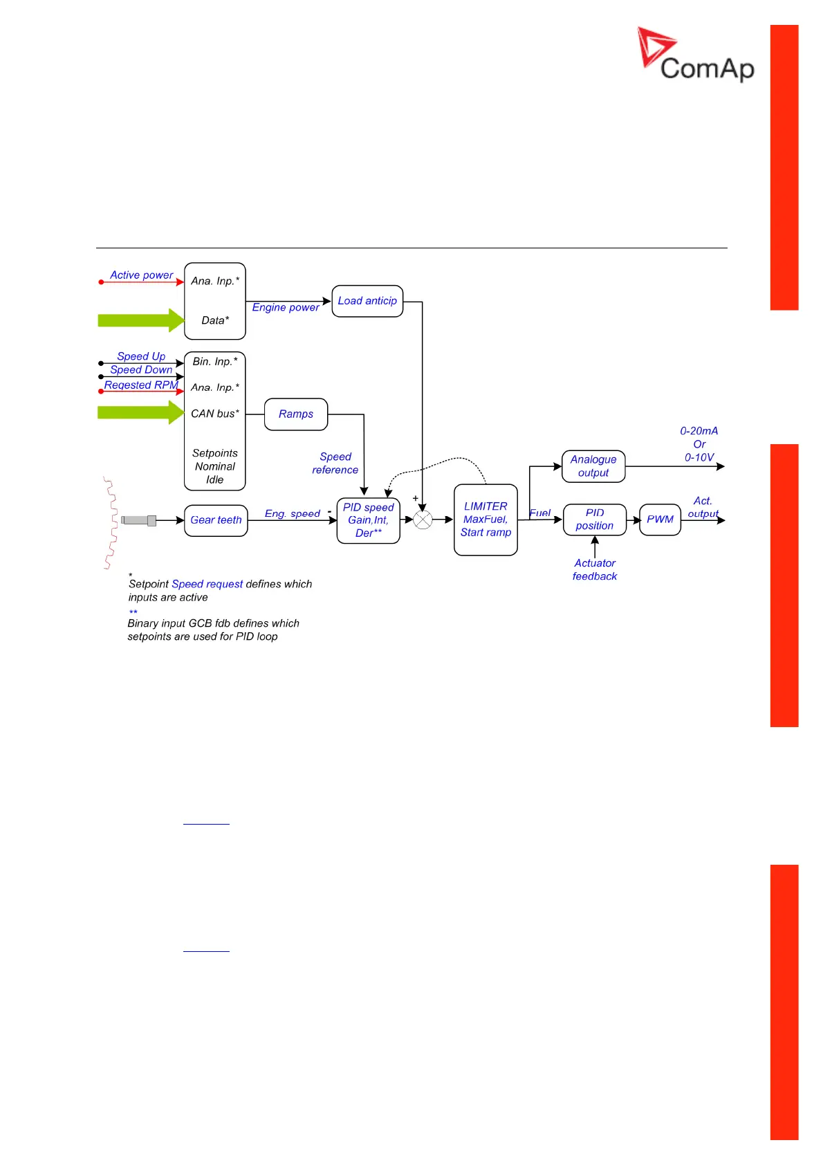
Block schematics – speed governor
Speed governor function in Idle or local load mode
ECON-4 compares the Reference and Actual speeds of the engine and calculates the Regulation
error.
The Actual speed is measured from the period of the signal generated by the magnetic pickup sensing
gears of the flywheel.
Speed reference can be generated by 3 ways:
a) by Binary inputs,
b) by Analogue input
c) from CAN bus,
see details at Table 6.
The Regulation error is then processed by the standard PID control structure with proportional,
integration and derivative parts. The PID setpoints – Gain, Int and Der define the quality of regulation.
The parameters of the PID control structure are different if the engine is in:
a) no-load operation,
b)
c) loaded operation
see details at Table 7.
The output of the PID control structure is then added together with the Load anticipation feedback,
which is directly proportional to the engine power. The output from the last sum is limited by the Anti-
windup Limiter module, which reduces the integrator’s output signal so that the sum of the signals
from the Gain, Integrator, Differentiator and Load anticipation blocks equals exactly the limit MaxFuel.