Accessory Modules for IL-NT, IC-NT, IA-NT and ID-Lite Global Guide
11
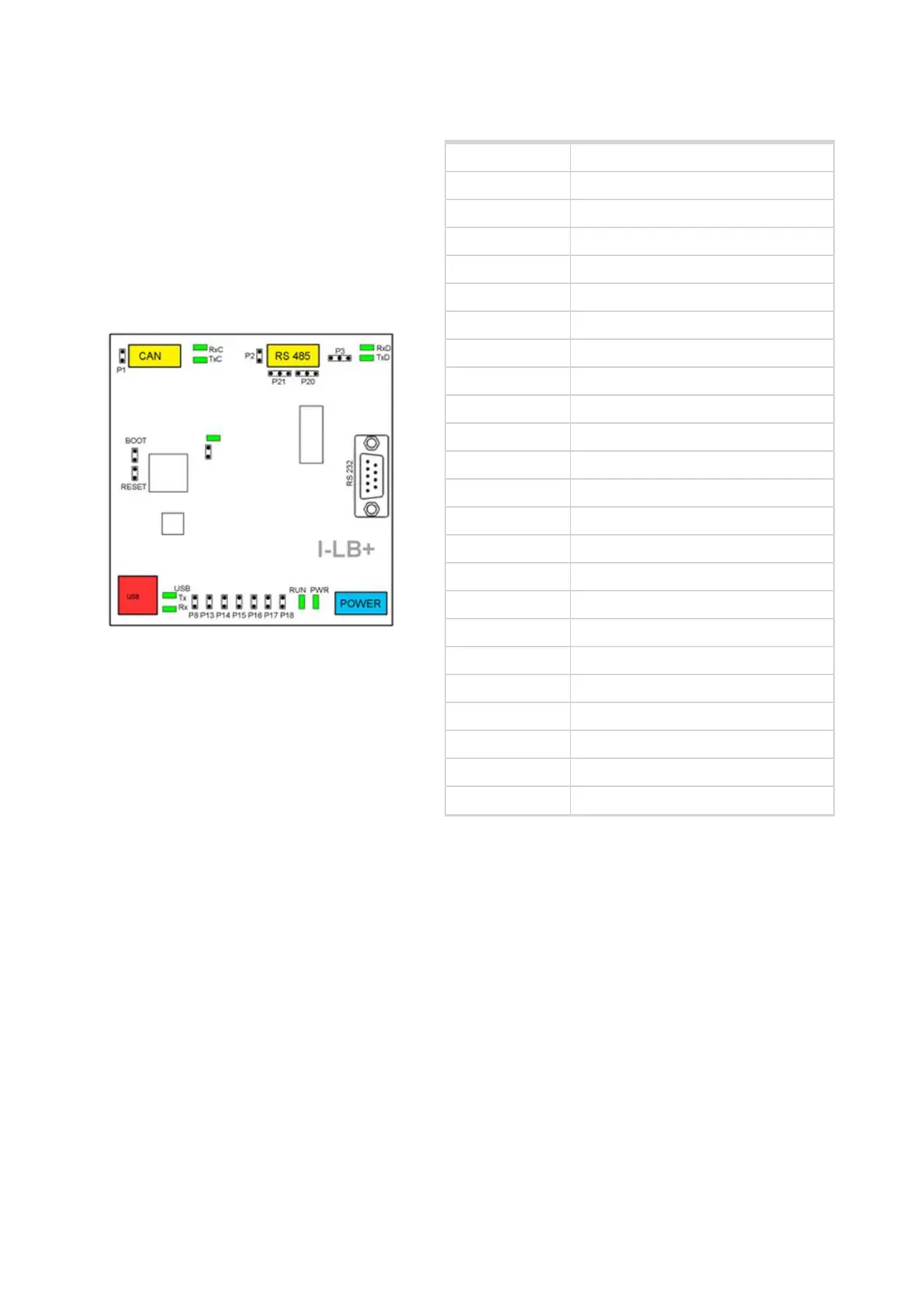
4.1.2 Connectors
POWER Power supply
CAN CAN 1 line
USB USB line
RS232 RS485 line
J13 - J18 SW/HW control
BOOT Programming
RESET Programming/Reset
P1 Terminating resistor
P2 Terminating resistor
P3 RS232 or RS485
P8 USB enable/disable
P13 Communication speed
P14 Communication speed
P15 Modem control (HW/SW)
P16 Protocol (Modbus/ComAp)
P17 CAN address
P18 Connection (direct/modem)
P20 Bias –A
P21 Bias –B
RxC, TxC CAN data
RxD, TxD RSxxx data
Tx, Rx USB USB data
RUN Power
PWR Module state
4.1.3 Address and jumpers settings
CAN1 termination (P1)
I-LB+ has included CAN terminating resistor (120 ohm). Close jumper P1 to connect terminating resistor to
CAN bus, open jumper P1 to disconnect terminating resistor.
RS232 or RS485 termination (P2)
I-LB+ has included RS232/RS485 terminating resistor (120 ohm). Close jumper P2 to connect terminating
resistor to RS485 bus, open jumper P2 to disconnect terminating resistor.
Select RS mode (P3)
Jumper P3 selecting RS mode. When jumper P3 is connected to 1-2, RS232 mode is activated. When jumper
P3 is connected to 2-3, RS485 mode is actives.