Accessory Modules for IL-NT, IC-NT, IA-NT and ID-Lite Global Guide
14
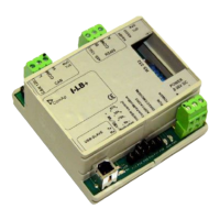
4.1.4 LEDs indication
LED Description State
RxC
No data are received on the CAN line Dark
Data are received on the CAN line Blink
TxC
No data are transmitted on the CAN line Dark
Data are transmitted on the CAN line Blink
RxD
No data are received on the RS232 or RS485 line Dark
Data are received on the RS232 or RS485 line Blink
TxD
No data are transmitted on the RS232 or RS485 line Dark
Data are transmitted on the RS232 or RS485 line Blink
TxUSB
No data are received on USB Dark
Data are received on USB Blink
RxUSB
No data are transmitted on USB Dark
Data are transmitted on USB Blink
RUN
No power supply Dark
Power supply OK Continuous light
PWR
When at least one controller is active on the CAN bus Continuouslight
After connection power supply - no controller detected on the CAN bus
(during communication speed detection).
Blink
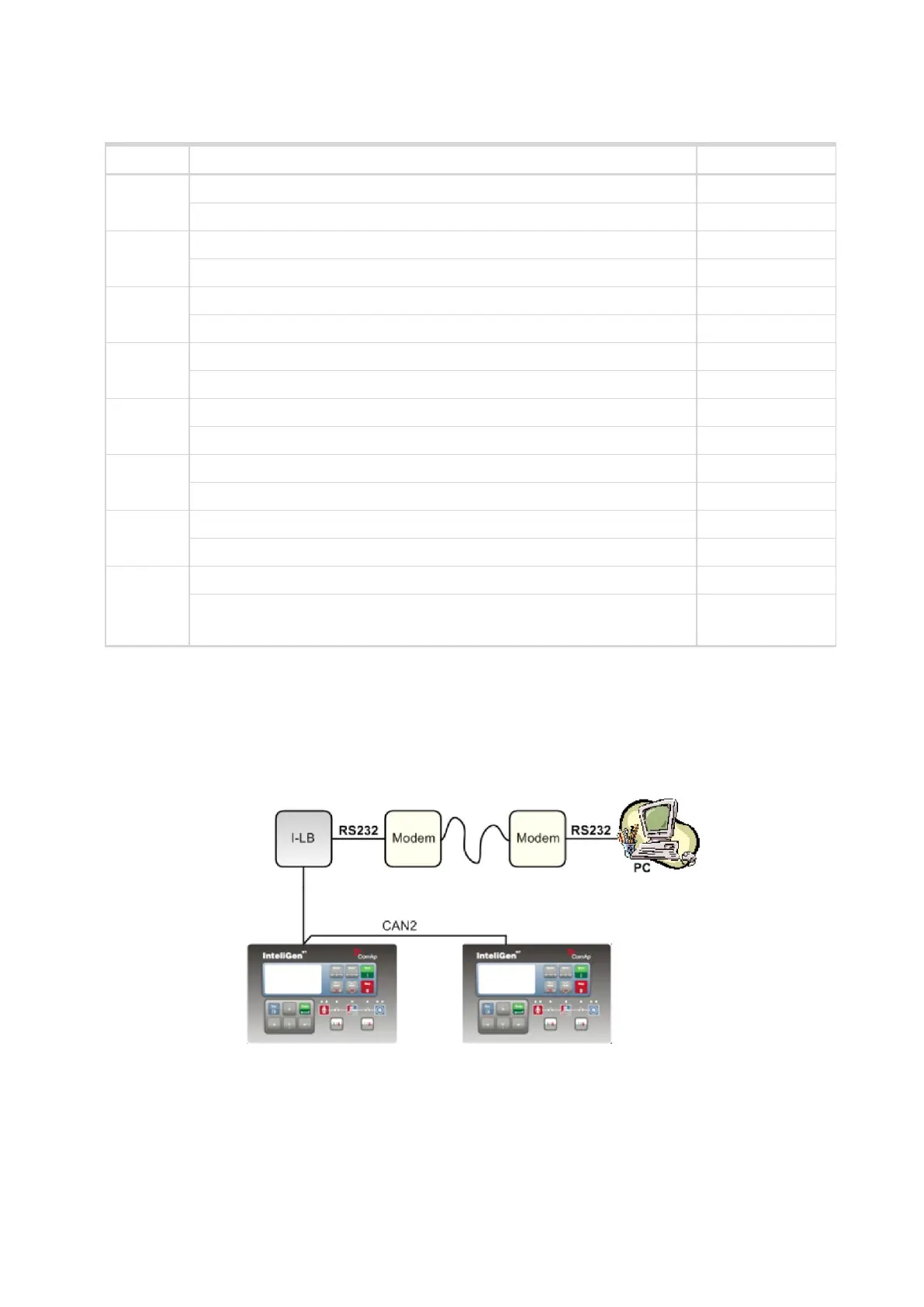
4.1.5 Wiring
I-LB+ has to be connected to modem via standard modem cable (full RS232) where the DSR (Data Set
Ready) signal detects modem presence (when MODEM (HW) type selected). Three-wire RS232 cable (TxD,
RxD, GND) can be used (e.g. for GSM modems) when MODEM (SW) type is selected.