Communication Guide, ©ComAp – March 2014 72
IGS-NT Communication Guide 03-2014.pdf
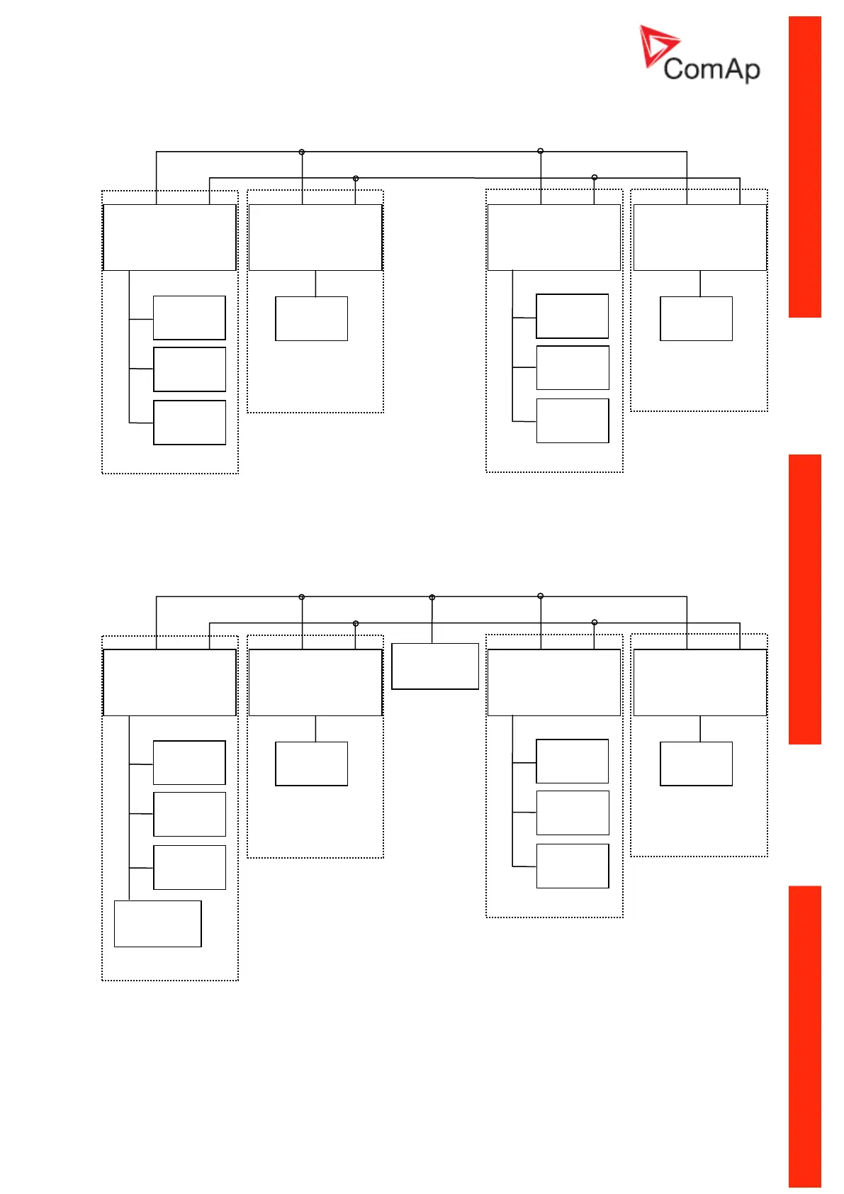
More controllers within common switchboard:
Connection of I-LB or other bridging modules:
Note: If I-LB (or other bridging module) is to monitor all the site, it is recommended to place it at the
position 1. If there is preferably monitored one group (within one switchboard) and the other controllers
not at all or only seldom, option 2 is more suitable. Remote connection to let’s say controller 7 is
possible in this case but data transfer will be quite slow.
INT CAN RS485
I-CR-R (1)
LOCAL CAN
INT CAN RS485
I-CR-R (2)
LOCAL CAN
INT CAN RS485
I-CR-R (3)
LOCAL CAN
INT CAN RS485
I-CR-R (4)
LOCAL CAN
INT CAN RS485
I-CR-R (1)
LOCAL CAN
INT CAN RS485
I-CR-R (2)
LOCAL CAN
INT CAN RS485
I-CR-R (3)
LOCAL CAN
INT CAN RS485
I-CR-R (4)
LOCAL CAN