For information regarding Comelit device models, see Appendix B - Device models.
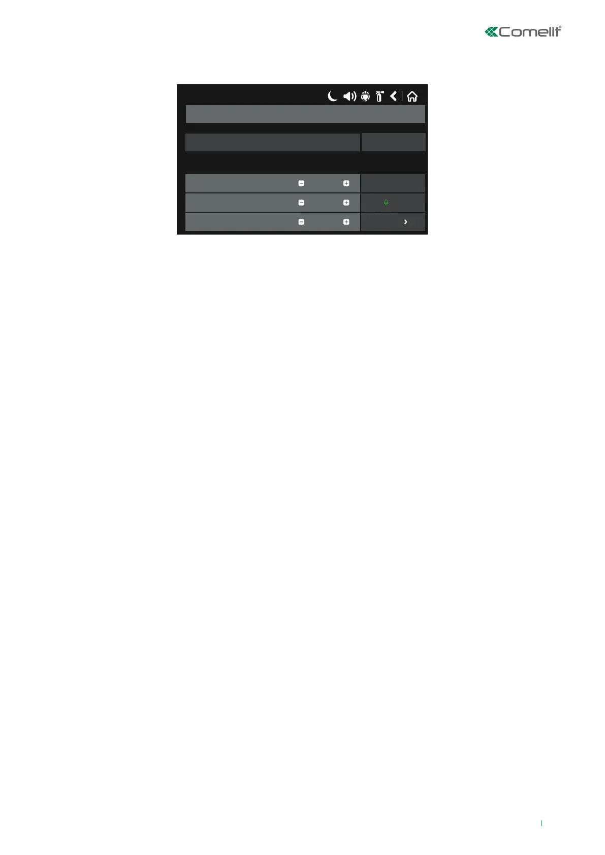
The figure shows the general view of the submenu for “new loop devices” (in the example, manual button 41PAM000).
17/06/2020 14:06
41PAM000 / 41PAE020
Address
Loop Number
Device Zone
1
2
1
EnabledNewDevice State
Save
More
Remove
OFF
Name
Description of the functions for buttons common to all devices (Fig. Screen 9):
• Save – Button for applying changes made to device parameters.
• Fix/Select type – The button becomes active when the panel recognises a dierent type of device to the one saved
previously.
• Enabled / Disabled – Button used to enable or disable a device (green for device enabled / yellow for device disabled);
CAUTION! When a loop device is disabled, the warning message “Loop Device Disabled” appears. Enabled devices are not
monitored by the panel. Sensor disabling is NOT reset after a panel reset, but only when the sensor is re-enabled.
• Remove – Button for removing the device from the system configuration.
• LED symbol on/off – Button for switching on the LED on the sensors (green for on / red for o); this is useful for identifying
an individual sensor or when searching for double addresses. On exiting the menu, the LED switches o automatically.
Note: Sounders Art. 41SAI000 and 41SAB100 do not have an LED; they can be identified by enabling audible indications.
Mini module Art. 41IOM010 does not have LEDs or audible indications.
• More – Button for showing additional device settings; these vary according to the device type. Fields common to all
devices are:
◊ LED Blink – Button for enabling or disabling LED blinking which indicates communication between the panel and the
device; when the status is set to ON, the device LED begins to flash every 10 seconds in normal operating mode.
Note: devices 41IOM010, 41SAI000 and 41SAB100 do not have LED indications to show communication with the panel.
◊ ID – This field shows the 10-digit “ID” used to identify the device within the system.
◊ Software Revision – This field shows the software revision of the device.
• Name – If this is pressed, the keypad screen used to enter the device name opens.
• Address (- / +) – Buttons for scrolling within the same loop; pressing the number of the current device allows direct entry of
the device number to search for.
• Loop Number (- / +) – Buttons used to select the number of the loop to which the device should belong; pressing the
number of the loop allows direct entry of the desired number.
• Device Zone (- / +) - Buttons used to select the number of the zone to which the device should belong; pressing the
number of the current zone allows direct entry of the desired number.
• Device State – Shows the current status of the device, as listed below:
◊ NEW (blue) - the device is new to the system. It should be saved using the “Save” button.
◊ NORMAL (green) - the device is working normally.
◊ FAULT (yellow) - the device is not responding. It can be deleted by pressing “Remove”.
◊ TYPE ERROR - a dierent type of device to the one saved previously has been identified.
◊ NONE – no device has been associated with the address.
29