24
COMPONENT IDENTIFICATION
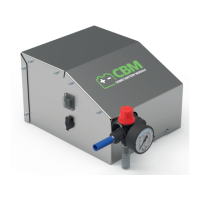
Refer to gures 1 to 5 at the beginning of the manual.
1 I/O switch 10 battery (optional)
2 EVERFLO motor pump 11 battery charger power cable
3 pressure regulation knob 12 battery charger
4 pressure regulation valve 13 battery charging cable with DIN 4165 plug
5 DIN4165 type battery charging socket 14 sprayer lance with nozzle
6 pressure gauge 15 delivery hose
7 module protection cover 16 by-pass hose (optional)
8 battery retention bracket 17 suction hose
9 reduction bracket for battery 18 identication label
CBM MODULE IDENTIFICATION LABEL
CAUTION
• If one or more labels should become damaged during use, contact the Manufacturer or
Specialist
Technician
for replacement.
The identication label (18) displays the model of the CBM module, serial number, year of manufacture
and the main electrical and mechanical specications (maximum pressure, weight, supply voltage,
consumption etc.).
SAFETY DEVICES
a) Pressure switch.
This device, calibrated by the Manufacturer, allows the maximum operating pressure to be limited,
preventing dangerous pressures from occurring when shutting o the delivery line or when attempting
to set pressures above maximum permitted values.
CAUTION
• The pressure switch is calibrated by the motor pump Manufacturer.
Do not recalibrate
.
b) Motor pump protection fuse.
This device stops operation of the motor pump in the event of overcurrent.
In the event of intervention, proceed as follows,
observing the instructions given in the manual of
the machine that incorporates the
CBM module:
• stop the machine and disconnect the power supply;
• purge any residual pressure from the high pressure circuit;
• replace the fuse (also refer to the section
“speCiFiCations anD teChniCal Data”;
• reconnect the power supply and repeat the start-up procedure.
CAUTION
• In the event of repeated intervention, do not use the motor pump (and therefore the machine that
incorporates it) without rst having it checked by a
Specialist Technician
.