30
• Pay particular attention to the information in the section
“warnings regarDing pumpeD ChemiCals”
.
• Do not pull the charger plug out of the power outlet by pulling the power cord.
• Keep the power cord, any extension cords, plugs and sockets dry. Do not touch them with wet hands.
• During operation:
- do not remove the protective cover of the CBM module
- do not use on hoses containing liquids under pressure.
- do not carry out maintenance procedures on the EVERFLO motor pump, the CBM module or the
machine that incorporates it.
• Follow the instructions in the section
“DesignateD use”
.
• Do not modify the assembly of the motor pump in any way. In particular, do not modify fastenings,
hydraulic ttings or protections.
• Do not deactivate or tamper with the controls and safety devices and the pressure limiter/control
valve.
Carry out procedures regarding the operations listed in the manual of the machine incorporating
the CBM module and on that of the EVERFLO motor pump that includes it; unless otherwise
indicated, the following must be recalled with regard to the motor pump.
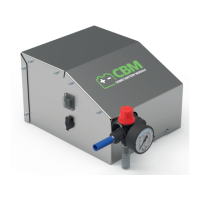
a. There is a start-up / shut-down I/O switch (1) on the CBM module.
b. The priming of the motor pump is possible only if the pressure in the delivery circuit is reset to
zero, which can be achieved by rotating the knob (3) of the valve (4) located on the CBM module.
c. The pressure can be regulated using the knob (3) of the valve (4) on the CBM module.
d. The pressure switch stops the motor pump each time delivery ow is interrupted (e.g. by shutting
o a lance); the motor pump begins working regularly once more when the delivery ow is restarted
(e.g. by opening lance ow).
WARNING
• To allow the motor pump to be primed rapidly, follow the procedure as described in part b) each
time it has to be re-primed.
• Do not allow the EVERFLO motor pump to run:
- if it is too noisy and/or if there are clear signs of water or oil leakage underneath it: if this is so, have
it checked by a
Specialist Technician
;
- exposing it to direct sunlight, with a temperature greater than 40°C.
SHUTDOWN, CLEANING AND STORAGE
CAUTION
•
Follow the instructions for shut-down, cleaning and storage in the manual of the machine
that incorporates the CBM module and the EVERFLO motor pump that includes it.
SHUTDOWN
CAUTION
• Check that, once the shut-down procedures have been carried out, no part of the motor pump and the
machine that incorporates it is in motion and that no hoses contain liquid under pressure.
Carry out procedures regarding shut-down listed in the manual of the machine that incorporates
the CBM module and on that of the EVERFLO motor pump that includes it; unless otherwise
indicated, the following must be recalled with regard to the motor pump.
1. Reset the delivery pressure as described in part c) of the section
“operation”
.