In the following wiring procedure, you will connect the power wires from the Hybrid Fiber Splice Box to a DC
Power Supply Unit (PSU).
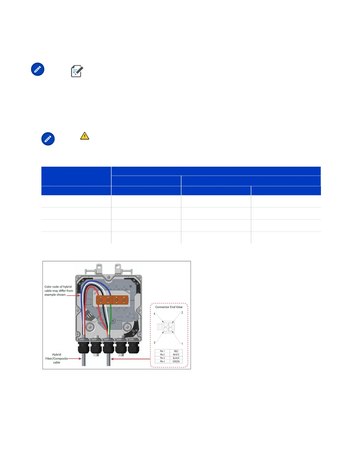
Note: The color code of the hybrid ber cable in the following tables and diagrams is for
example purposes only. The color of the wires may be dierent than the examples depending on the
type and manufacturer of the composite hybrid cable.
1. Refer to Table 7: 4-Wire Power Wiring with LPS (page 27) and Figure 4: Wiring a Hybrid Fiber Splice Box
for 4-Wire Power with LPS (page 27) to wire a Hybrid Fiber Splice Box for 4-Wire power with Limited
Power Source (LPS).
Note: All four pins of the proprietary UAP2 4-pin -42 to -57 Vdc Power connector must be
terminated.
TABLE 7: 4-Wire Power Wiring with LPS
Hybrid Cable Two
Circuits
UAP2 Power Cable
Connector
Wire Wire Pin Funcon
Circuit 1 (0V) Red 1 V1+
Circuit 1 (-42 to -57V) White 2 V1-
Circuit 2 (0V) Black 3 V2+
Circuit 2 (-42 to -57V) Green 4 V2-
FIGURE 4: Wiring a Hybrid Fiber Splice Box for 4-Wire Power with LPS
2. Aer you have wired the Hybrid Fiber Splice box, complete the steps in Mounng a UAP2 on a Ceiling or
Mounng a UAP2 on a Wall.
DRAFT: CONFIDENTIAL
Chapter 4: Mount the Fiber UAP2
CommScope ERA
®
UAP2 with Fiber Interface Installaon Guide , Release
P/N M0203AB, DRAFT Rev D 27