Do you have a question about the Compaq DESKPRO 386 and is the answer not in the manual?
Overview of specifications for system components and options for the Compaq Deskpro 386.
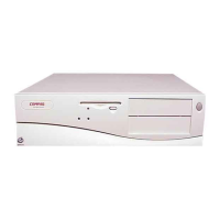
Detailed specifications including dimensions, weight, and environmental requirements for the system unit.
Technical specifications for the 360-Kbyte 5.25-inch diskette drive.
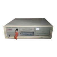
Specifications for the 300/600-megabyte fixed disk drive expansion unit.
Explains the automatic diagnostic tests run when the system is turned on.
Provides a flowchart for quick identification and correction of POST error conditions.
Outlines the situations that require running the system SETUP program.
Provides step-by-step instructions for executing the system SETUP program.
Lists preparatory steps required before running the ADVANCED DIAGNOSTICS program.
Details the various diagnostic tests available for selection in the program.
Lists ADVANCED DIAGNOSTICS error codes, probable causes, and recommended actions.
Explains memory error codes and their relation to specific memory locations.
Explains the structure and usage of the illustrated parts catalog.
Lists spare parts available in the U.S. with their corresponding part numbers.
Overview of module-level procedures for removing and replacing components.
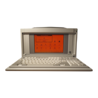
Procedures for removing and replacing COMPAQ monitors.
Steps to remove and replace the system unit power supply assembly.
Procedure for removing and replacing the main system board.
Overview of switch and jumper locations on various system boards and controller boards.
Diagrams and information on system board switch settings and component locations.
Jumper settings for the 32-bit system memory board.
Explains options for expansion units: maximum storage, mirroring, and duplexing.
Steps for setting up the external expansion unit using FDISK and EXTDISK utilities.
| Processor | Intel 80386 |
|---|---|
| Operating System | MS-DOS |
| Ports | Serial, parallel |
| RAM | 1 MB to 16 MB |
| Floppy Drive | 5.25" or 3.5" |