25
Figure # 16 Temporary Buttons
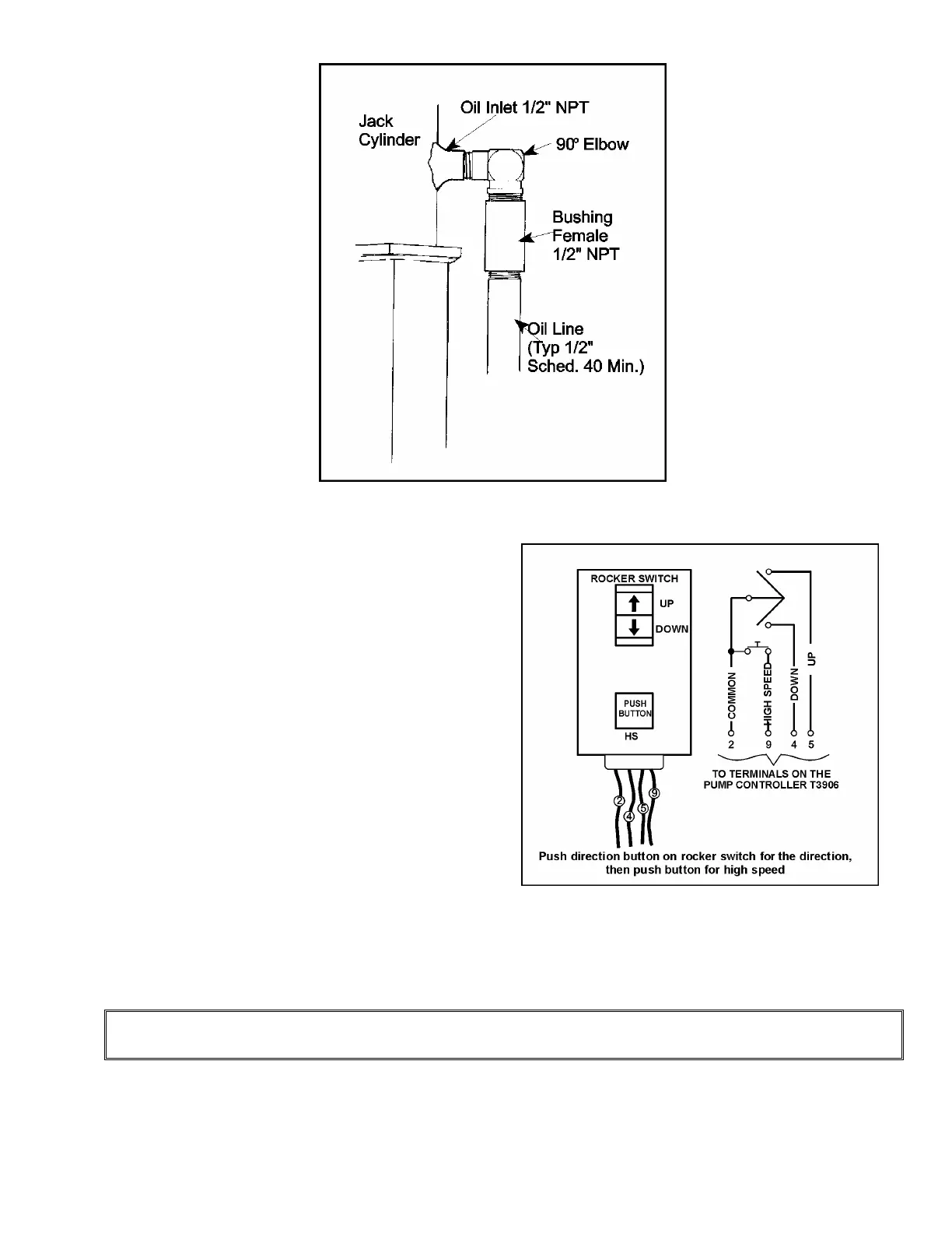
Figure # 15 Steel Oil Line Connection to Jack
8) Temporarily wire and connect a set of
buttons (located on the end of a 25 foot
cord) to the pump unit control box as
follows: The UP wire is connected to #
5; the DOWN wire is connected to # 4;
the COMMON wire is connected to # 2.
For HIGH SPEED, connect to Terminal
# 9. The temporary buttons consist of
an UP button, a DOWN button and a
HIGH SPEED button. A rocker switch
and a single push button for HIGH
SPEED work well. Press the UP button
to travel UP SLOW SPEED. Press the
HIGH SPEED button while the UP
button is pressed, and the valve will
switch into HIGH SPEED mode.
Release the HIGH SPEED button, and
the valve will return to UP SLOW
SPEED mode. Use the same procedure for the DOWN direction. These connections are
made on the Series 8000 PC Board and are wired to the T3906 screw terminals inside
the control panel in the machine room.
NOTE
Refer to section called, "Electrical Installation" for pump connection.
9) The hydraulic system is now ready for start-up. Before starting up, however, first confirm
the following: