10
LOCAL CODES AND REGULATIONS MAY REQUIRE A
LICENSED ELECTRICIAN TO CONNECT TO THE
MAINS. CHECK WITH YOUR LOCAL AUTHORITY
BEFORE BEGINNING THE WORK.
Instruct the electrician as to the proper location for the installation of the following:
a) Install a fused, lockable, disconnect switch with the proper amperage and voltage supply,
as detailed on the Pump Unit Data Plate -- or main layout drawing, if provided. The
disconnect must be fused.
b) Install a fused, lockable, disconnect switch or breaker for the cab lighting supply. The
disconnect must be fused.
c) Pit light, switch and receptacle. (Optional but may be required by local code.)
NOTE
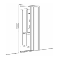
The arrangement shown in Figure # 1 is for clarification only. Actual placement of the
disconnect switches will have to conform to local codes and regulations.
RAIL BRACKETS AND RAILS INSTALLATION
NOTE
The importance of accurately installing the rails cannot be over stressed. The rails must be
supported and aligned properly. They must be true and plumb. The overall performance and
“ride” of the lift depend primarily on how well the rails are installed.
1) Start by plumbing the hoistway to determine the tightest spot in order to establish your
running clearances and the overall condition of the rail bracket wall.
2) Install the rail brackets (See Figure # 3) by starting at the location of the top most bracket.
First, find the centerline of the rails as referenced from the “sill line” from the
Site Layout
Drawing
. Mark the centerline location and, then, drop a plumb from this point. Be as
accurate as possible here and verify that your measurements are within +/- 1/32". “Snap”
a “chalked” plumb line to mark the centerline from the top to the bottom of the shaft.
3) Prepare a 4 foot carpenter’s level in the following way to be used as a “template” to mark
the location of the rail bracket holes. Use a small tip black permanent ink marker for this
purpose. On the carpenter’s level mark the centerline and the position of each bracket
hole to be drilled in the wall. (See Figure # 2). Use the appropriate D.B.G. as indicated on
your Site Layout Drawing.