11
4) Locate rail brackets and identify the two (2) or three (3) special rail brackets that support
the upstand post and jack unit. (These two rail brackets have an angle or threaded rod
welded to the inside center). Mark all rail brackets on the inside showing the exact center
between the two fixed (welded) angles. This mark will be “lined up” with the centerline that
you found and marked in step # 2 above.
5) Using the centerline that you found and marked in step # 2 and the center you marked on
the rail bracket in step # 4, descend to each level and mark where each rail bracket is to
be fastened to the wall. The number of brackets and their locations are shown on the
Site Layout Drawing
. Vertical bracket spacing distances of upper brackets are not
critical; therefore, if there is a depression or immovable obstruction on the wall where the
bracket is to be placed, then the bracket may be moved up or down to miss the
obstruction. However, the location of the rail brackets that support the upstand and the
hydraulic jack are critical and must be accurately placed per the Site Layout Drawing.
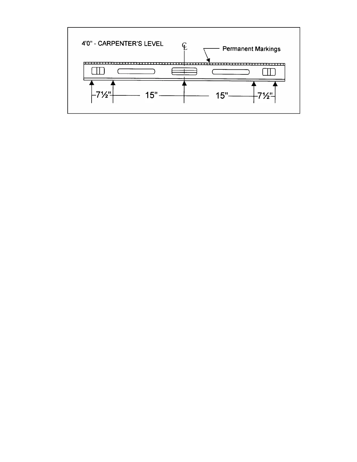
6) At each bracket location, use the prepared 4 foot carpenter’s level to mark the position of
the rail bracket mounting holes. Place the marked center point of the level even with the
marked center of the rail bracket on the wall. Ensure that the level is “level” and then,
mark the location of each rail bracket hole. Repeat this procedure at each rail bracket
location.
7) Drill holes and then fasten each rail bracket to the wall. Wall fasteners may be either
Thru-Bolts, Concrete Anchors, Lag Bolts (for wood walls - min. 1/2"), or “Epoxy Fill”
Anchors (for block walls). Check your Site Layout Drawings. Note that if Thru-Bolts are
supplied, they will be shipped “uncut” to allow you to properly size them to best fit your
particular job. They are shipped to you in three (3) foot lengths of threaded rod with a 3" x
3" plate attached to each end.
CAUTION: The rail brackets that support the upstand post and the hydraulic jack are
different from the standard rail brackets and must be identified and placed at their correct
respective locations. Refer to Site Layout Drawing.
8) Cut off excess threaded rod protruding from the rail bracket bolts.
Figure # 2 4 Foot Level Prepared As Template