FAILURE TO CREATE A SEAL TO THE FIREBOX WITH THE EXHAUST COLLAR ASSEMBLY WILL CAUSE
THE APPLIANCE TO FUNCTION IMPROPERLY AND CAN CAUSE INJURY OR PROPERTY DAMAGE.
A. Remove the safety barrier and glass door (see "safety barrier/door removal and installation" section).
B. Remove the contents from the firebox and set aside. You will need the exhaust and air inlet collar.
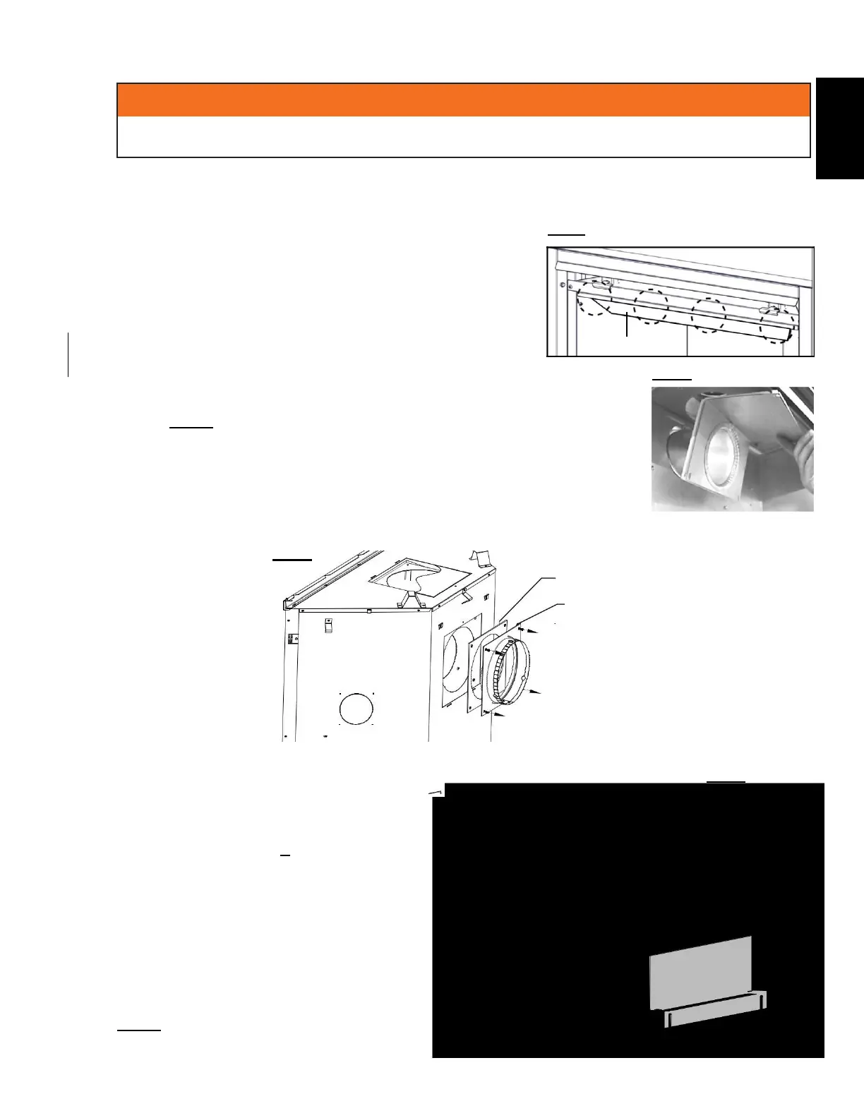
C. To ease assembly, remove the 4 hex head screws securing the deflector from inside the top front of the
firebox (FIG 1). FIG. 1
D. Place the gasket (provided with the 4" collar
assembly) over the 4" (101.6mm) flue collar and
bend along perforation (FIG 2).
From inside the firebox, insert the 4" (101.6mm) flue collar
through the back of the firebox. Install the rear exit shield
onto the 4" (101.6mm) flue collar (see "rear exit shield (for
rear vent only)" section).
Secure the flue collar assembly, gasket, and rear exit shield using the 4 black
pan head 5/8" thread cutting screws (FIG 2).
NOTE: Do not overtighten. The gasket only needs to be snug
against the firebox.
G. Re-attach the deflector using the 4 screws, and install the log set, glass
door, and safety barrier.
H. Install the 7" collar assembly, complete with gasket, onto the rear panel
around the 4" (101.6mm) collar with the screws provided (FIG 3).
FIG. 3
GASKET
3.12 rear exit shield (for rear vent only)
A. Remove the safety barrier and door from
the appliance (see “safety barrier & door
removal/installation” section).
B. Loosen the 2 screws that secure the
exhaust plate, and slide the shield's
slotted openings behind the
screwheads. Tighten the 2 previously
loosened screws (FIG 1).
C. Reinstall the door and safety barrier
assembly on the appliance (see
“safety barrier & door
removal/installation” section).
NOTE: This shield is used to block the
view through the venting to the outdoors.
INTAKE COLLAR
ASSEMBLY
FIG. 1
W415-1679 / D / 03.09.18