24
3.13 top exit
FAILURE TO CREATE A SEAL TO THE FIREBOX WITH THE EXHAUST COLLAR ASSEMBLY WILL
CAUSE THE APPLIANCE TO FUNCTION IMPROPERLY AND CAN CAUSE INJURY OR PROPERTY
DAMAGE.
NOTE: This appliance has been factory shipped as a rear vent.
A. Remove the safety barrier and glass door (see "safety barrier & door
removal/installation" section).
B. Remove the contents from the firebox and set aside.
You will need the exhaust and air inlet collar.
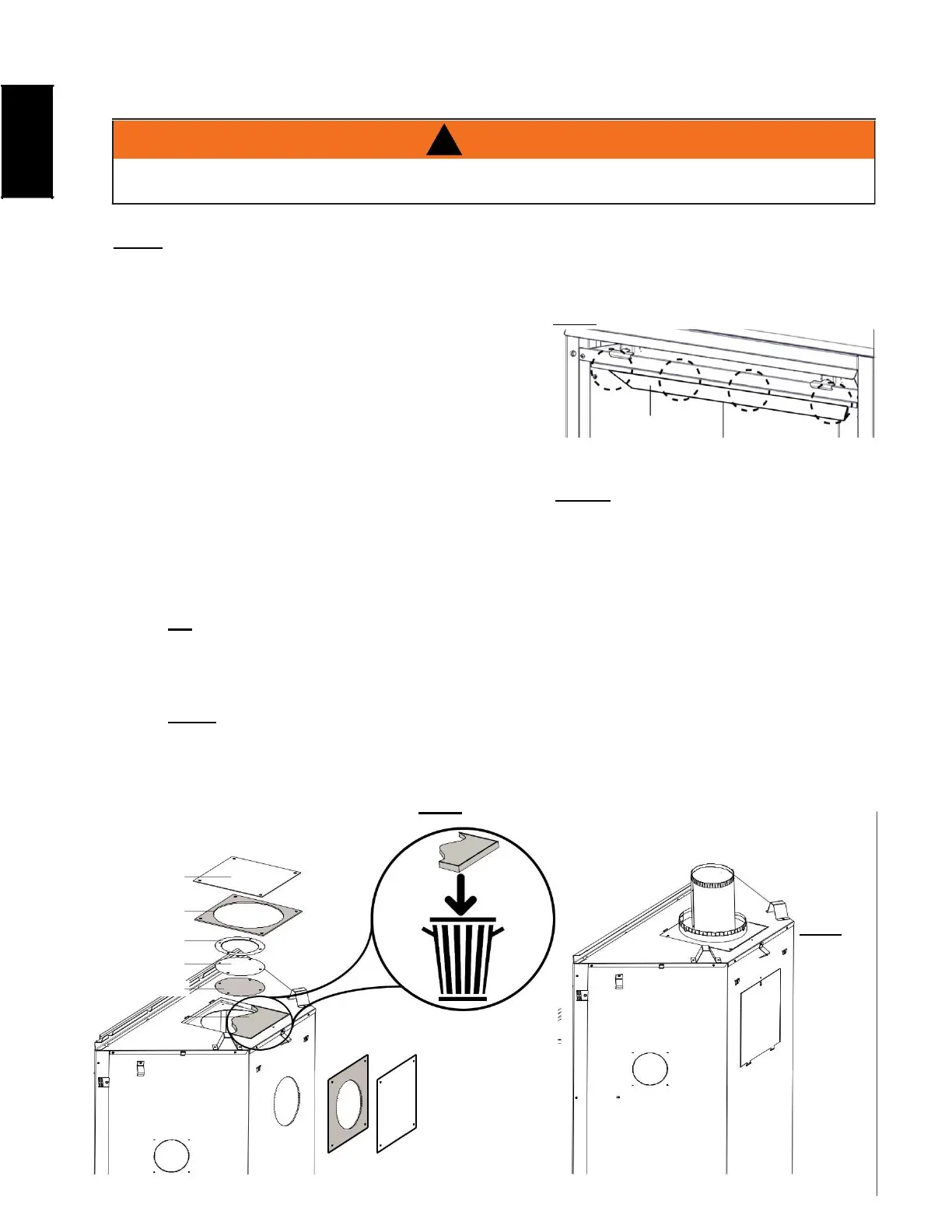
C. To ease assembly, remove the 4 hex head screws,
securing the deflector from inside the top front of
the firebox (FIG 1).
D. Remove the outer cover plate and gasket by removing
DEFLECTOR
the 4 screws. Install the outer cover plate and gasket onto the back of the appliance using the 4
previously removed screws (FIG 2).
E. Remove the 1 1/2" (38.1mm) thick batt of insulation and discard (FIG 2).
F. Remove the 4 screws securing the inner cover plate, 'o' ring (CX36-1 only), and gasket. Remove the
inner cover plate and discard (FIG 2).
G. Reinstall the 'o' ring (CX36-1 only) and gasket into the appliance using the previously removed screws (FIG 2).
H. Place the 7" (177.8mm) intake collar and gasket onto the top of the appliance and secure using 4 screws.
TIP: The manual baggie supplies the gasket (CX36-1 only) and screws (packaged in another
separate baggie).
I. From inside the firebox, install the 4" (101.6mm) exhaust collar with gasket up through the top of
the firebox, and secure with the the 4 hex head 3/4" black screws supplied in the manual baggie.
NOTE: Do not overtighten. The gasket only needs to be snug against the firebox.
J. Reinstall the top deflector, log set, glass door, and safety barrier.
FIG. 2