26
4.1.1
EN
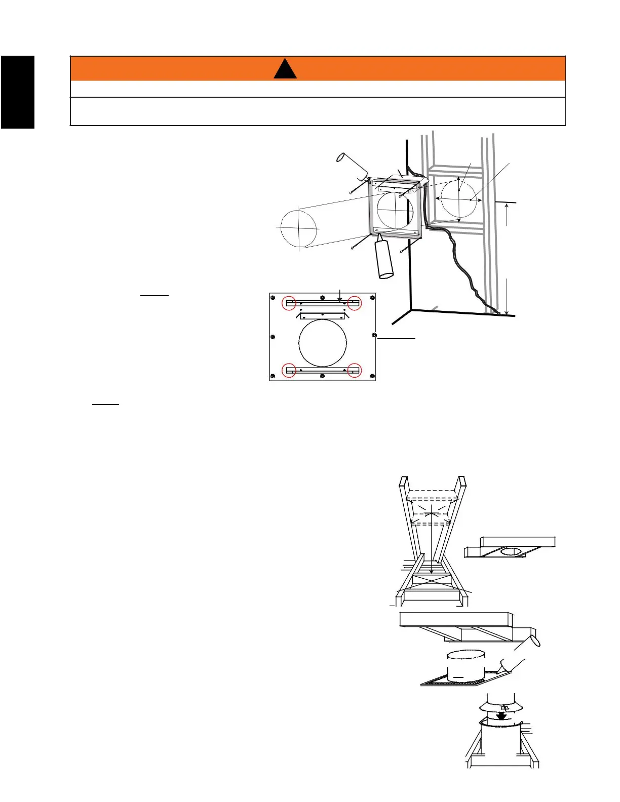
horizontal installation
! WARNING
THE FIRESTOP ASSEMBLY MUST BE INSTALLED WITH THE VENT SHIELD TO THE TOP.
TERMINALS MUST NOT BE RECESSED INTO A WALL OR SIDING MORE THAN THE DEPTH OF THE
RETURN FLANGE OF THE MOUNTING PLATE.
This application occurs when venting through
an exterior wall. Having determined the
correct height for the air terminal location, cut
and frame a hole in the exterior wall
as illustrated to accommodate the fi restop
assembly. Dry fi t the fi restop assembly
before proceeding to ensure the brackets on
the rear surface fi t to the inside surface of
the horizontal framing.
The vent shield must be installed to the full
depth of the combustible wall. The length
of the vent shield may be cut shorter for
combustible walls that are less than 8 1/2"
(216mm) thick. NOTE: Bend the tabs for
reduced side clearances or move the shield
for reduced top clearances.
A. Apply a bead of caulking (not supplied)
around the corner edge of the inside
surface of the fi restop assembly, fi t
the fi restop assembly to the hole and
secure using the 4 screws (supplied in
your manual baggie).
NOTE: The above is for illustration
purposes only. Vents do not
always pass through center of
frame.
NOTE : Do not fill the air space between the firestop spacer and the exterior wall with any type of
insulating material (i.e., spray foam).
B. Once the vent pipe is installed in
its fi nal position, apply red RTV silicone sealant (W573-0002) (not supplied) between the pipe and
the fi restop.
4.1.2 vertical installation
This application occurs when venting through a roof. Installation kits
for various roof pitches are available from your authorized dealer /
distributor. See accessories to order specific kits required.
A. Determine the air terminal location, cut and frame a square opening
as illustrated in the ceiling and the roof to provide the minimum 1"
(25mm) clearance between the vent pipe and any combustible
material. Try to center the vent pipe location midway between two
joists to prevent having to cut them. Use a plumb bob to line up the
center of the openings. A vent pipe shield will prevent any materials
such as insulation, from filling up the 1" (25mm) air space around the
pipe. Nail headers between the joist for extra support.
FIRESTOP
UNDERSIDE OF
JOIST
B. Apply a bead of caulking (not supplied) to the framework or to the
Wolf Steel vent pipe shield plate or equivalent (in the case of a finished
ceiling), and secure over the opening in the ceiling. A firestop must be placed
on the bottom of each framed opening in a roof or ceiling that the venting
system passes through. Apply a bead of caulking all around and place a
firestop spacer over the vent shield to restrict cold air from being drawn into the
room or around the fireplace. Ensure that both spacer and shield maintain the required
clearance to combustibles. Once the vent pipe is installed in its final position, apply
Mill Pac sealant (W573-0007) (not supplied) or red RTV silicone (W573-0002) (not
supplied) between the pipe and the firestop assembly.
In the attic, slide the vent pipe collar down to cover up the open end of the shield and
W415-1679 / D / 03.09.18