4.2.3 appliance vent connection
29
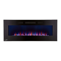
A. Install the inner exhaust fl ue collar to the appliance. Secure
with a minimum of 3 #8 screws. Seal the joint and screw holes
using Mill Pac sealant (W573-0007) (not supplied).
B. Install the outer fl ex pipe to the appliance. Attach and
seal the joints using a red RTV silicone and a minimum of
3 #8 screws.
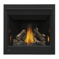
4.3 using rigid vent components
#8 X 1/2”
SELF
DRILLING
SCREWS
EN
2” (50.8mm)
OVERLAP
HIGH TEMP
SEALANT
The vent system must be supported approximately every 3 feet (0.9m) for both vertical and horizontal runs.
Use Wolf Steel Ltd. support ring assembly or equivalent noncombustible strapping to maintain the minimum
clearance to combustibles for both vertical and horizontal runs.
All inner exhaust and outer intake vent pipe joints may be sealed using either red high temperature
silicone sealant (W573-0002) (not supplied) or black high temperature sealant W573-0007 Mill Pac (not
supplied) with the exception of the appliance exhaust flue collar which must be sealed using Mill Pac.
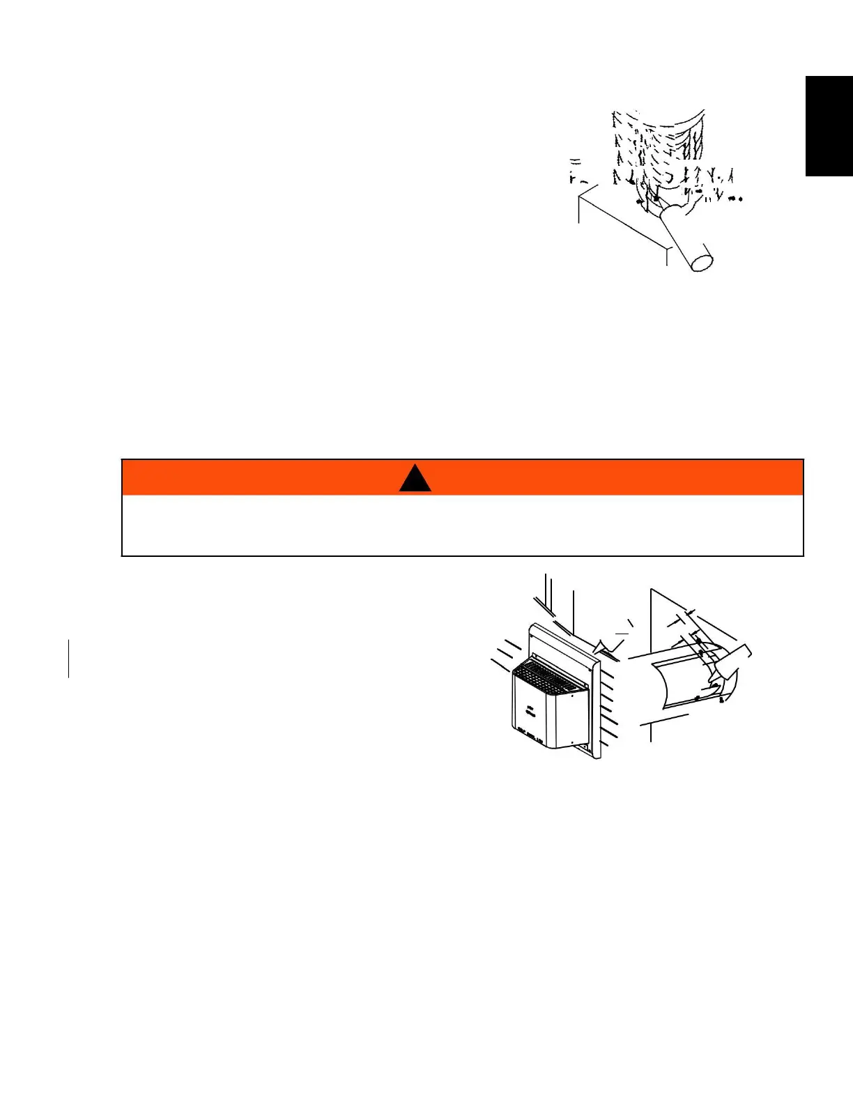
4.3.1 horizontal air terminal installation
! WARNING
RISK OF FIRE, DO NOT ALLOW LOOSE MATERIALS OR INSULATION TO TOUCH THE VENT
PIPE. REMOVE INSULATION TO ALLOW FOR THE INSTALLATION OF THE ATTIC SHIELD
AND TO MAINTAIN CLEARANCES TO COMBUSTIBLES.
Move the appliance into position. Measure the
vent length required between terminal and
appliance taking into account the additional
length needed for the fi nished wall surface
and any 1” (25.4mm) overlaps between venting
Apply high temperature sealant W573-0007 Mill Pac
(not supplied) to the outer edge of the inner exhaust
fl ue collar of the appliance. Attach the fi rst inner
rigid pipe component and secure using a minimum of
3 self tapping screws. Repeat using the outer rigid pipe.
C. Insert the vent pipes through the fi restop maintaining the required clearance to combustibles. Holding
the air terminal (lettering in an upright, readable position), secure to the exterior wall and make
weather tight by sealing with caulking (not supplied).
The air terminal mounting plate may be recessed into the exterior wall or siding no greater than the
depth of the return flange.
W415-1679 / D / 03.09.18