53
10.1 pilot burner adjustment
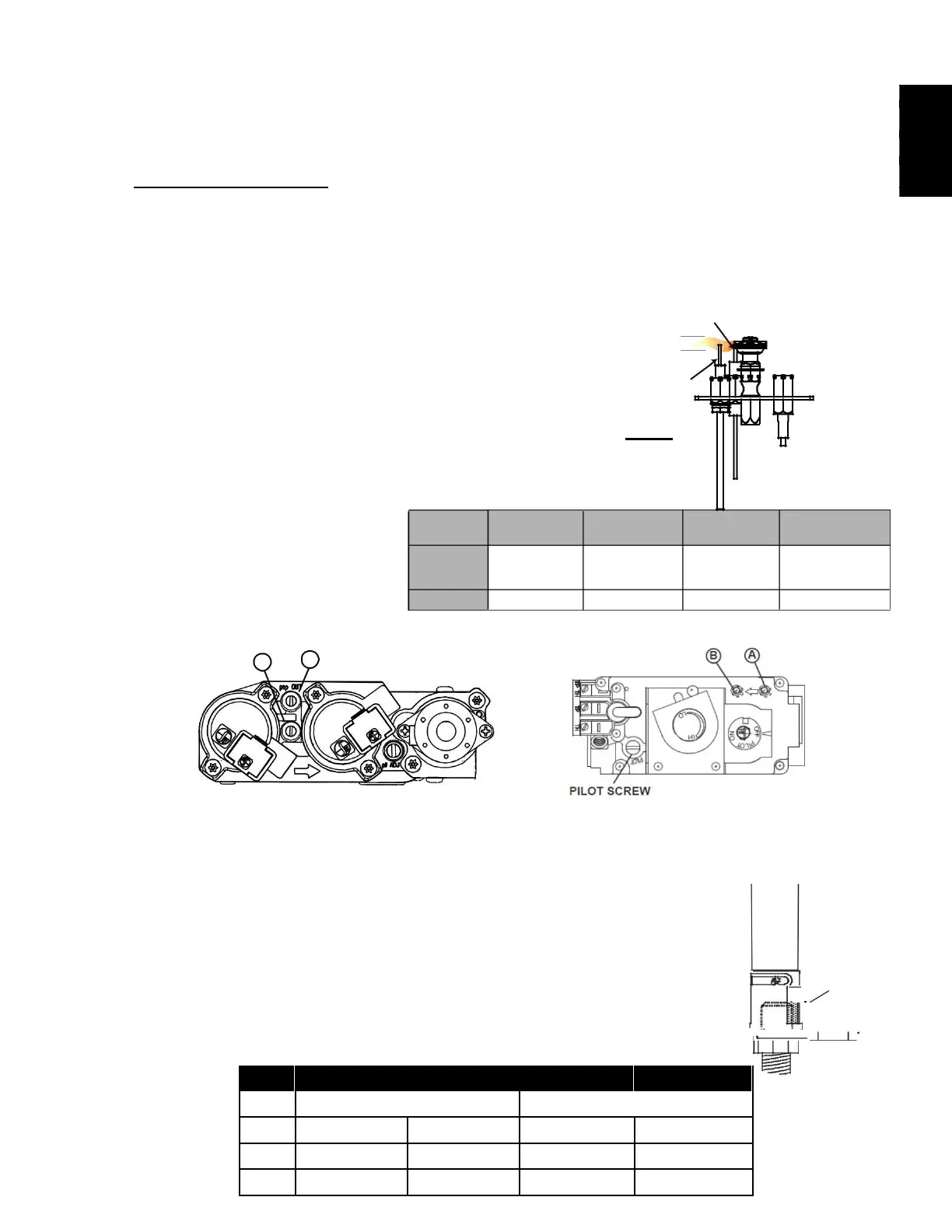
Adjust the pilow screw to provide properly sized flame. Turn in a clockwise direction to reduce the gas flow.
Inlet pressure can be checked
by turning screw A counter-clockwise 2 or 3 times, and then placing the pressure
gauge tubing over the test point. The gauge should read as described on the chart below. Check pressure with
the main burner operating on "HI".
Outlet pressure can be checked the same as above using screw B. The gauge should read as described on the
chart below. Check pressure with the main burner operating on "HI".
screw (B). Gauge should read as described on the chart
below. Check pressure with main burner operating on “HI”.
AFTER TAKING PRESSURE READINGS, BE SURE TO
AFTERTURNSCREWSTAKING PRESSURECLOCKWISEREADINGS,FIRMLYTOBERESEALSURETO.DO
TURNNOTOVERSCEWS-TORQUECLOCKWISE. FIRMLY TO RESEAL. DO
Leak test with a soap and water solution.
Leak test with a soap and water solution.
Prior to pilot adjustment, ensure that the pilot assembly
has not been painted. If overspray or painting of the pilot
UPPER 3/8” (9.5mm) TO 1/2”
assembly has occurred remove the paint from the pilot
assembly, or replace. Fine emery
cloth or a synthetic scrub pad (such as
Scotch-Brite™) can be used to remove
the paint from the pilot hood, electrode
*Maximum inlet pressure not to exceed 13”.
A B
10.2 venturi adjustment
This appliance has an air shutter that has been factory set open according
to the chart below:
Regardless of venturi orientation, closing the air shutter will cause a more
yellow flame, but can lead to carbonization. Opening the air shutter will
cause a more blue flame, but can cause flame lifting from the burner ports.
The flame may not appear yellow immediately; allow 15 to 30 minutes for
the final flame colour to be established.
AIR SHUTTER ADJUSTMENT MUST ONLY BE DONE BY A QUALIFIED
VENTURI
BURNER
AIR
SHUTTER
OPENING
ORIFICE
W415-1679 / D / 03.09.18