Dinverter
A
User Guide
Issue code: d2au9
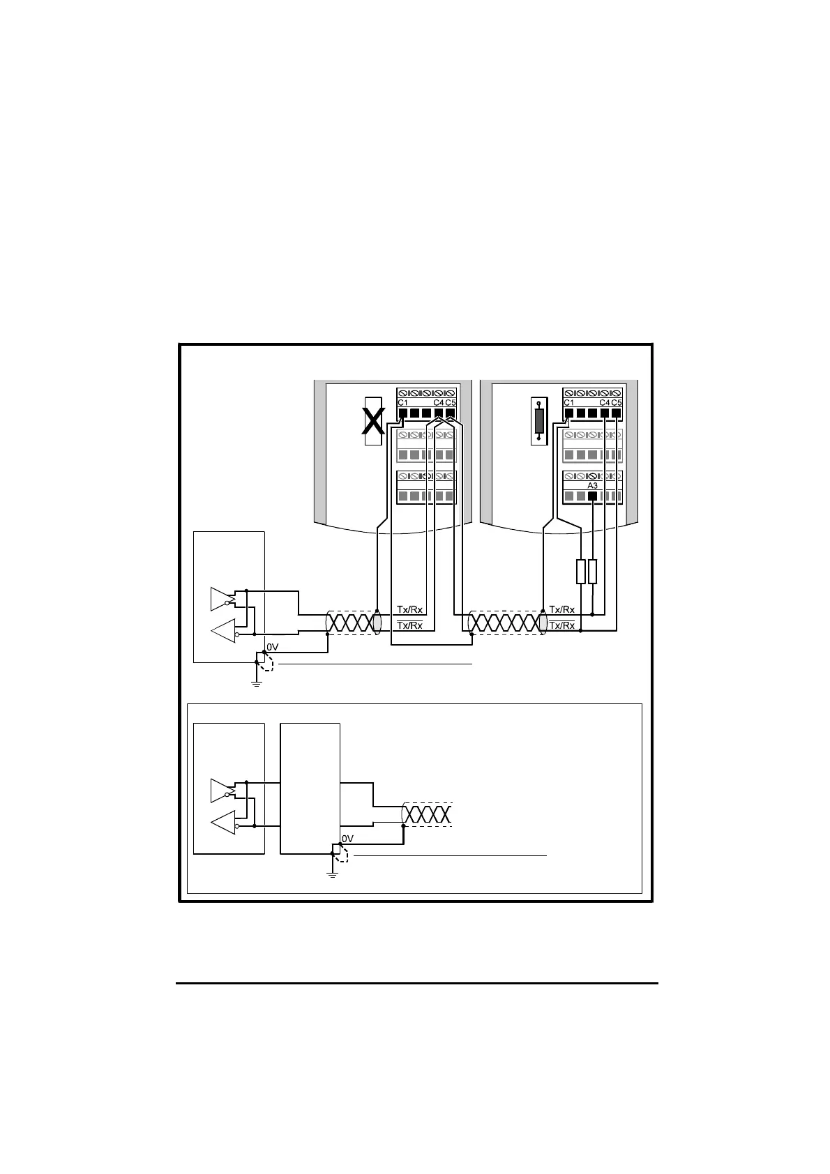
3 The serial communications cable must be shielded. The shield(s) must
be connected as shown in Figure 4–12.
4 Ensure the total cable length does not exceed 1200 metres
(4,000 feet).
For detailed information on using the Drive with serial communications, see
the Dinverter A Technical Reference Manual.
2.2kΩ
±10%
System
controller
(RS485
transceiver)
Termination
resistor fitted
Termination
resistor removed
Isolation
unit
First or
intermediate
Drive on the
serial link
Last Drive on
the serial link
Connect an external link if no internal
connection exists in the transceiver
between 0V and ground
System
controller
(RS485
transceiver)
Connect an external link if no internal
connection exists between isolated 0V
and ground
Transceiver and isolation unit (if required)
Figure 4–12 RS485 2-wire serial communications connections