Dinverter
A
User Guide
Issue code: d2au9
52
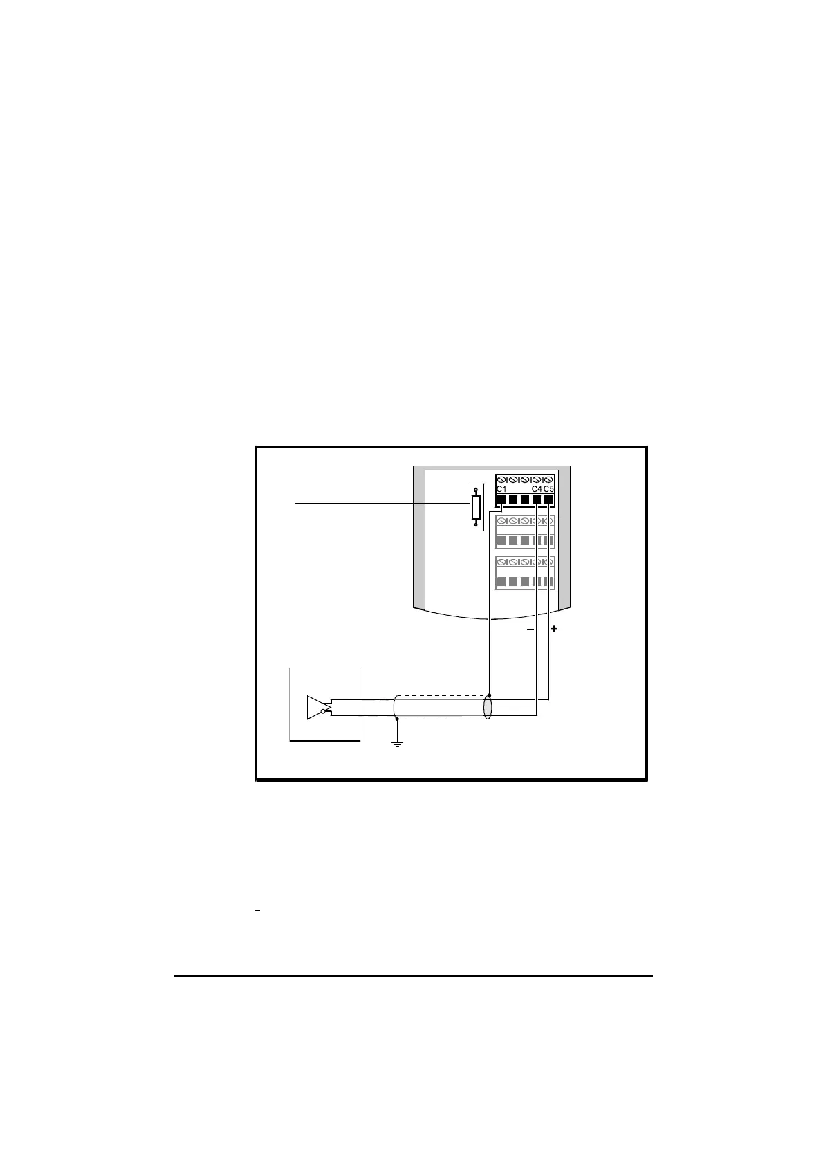
Connecting a remote speed reference
1 Make a note to set parameter 0.25 at 0.20, 20.0, 4.20 or 20.4.
2 When a signal current is applied to terminals C4 and C5, a voltage is
developed across the terminals due to the input resistance supplied by
the termination resistor. The full-scale voltage is 2V which is produced
when the input current is 20mA and the termination resistor is 100Ω.
3 If a different input current is required to produce 2V full-scale voltage,
the 100Ω termination resistor can be replaced with a 0.5W resistor of a
suitable value.
4 If the Drive is used with the resistor removed, the input can be used as
a unipolar voltage input having a 2V full-scale value. Parameter 0.25
must then be set at
0.20 for 0-to-2V operation, or at 20.0 for 2V-to-0
operation.
Remote
speed-reference
Termination resistor
Figure 4–13 Remote speed-reference connections
Connecting a motor thermistor to terminals C4 and C5
1 Make a note to set parameter 0.25 at th.
2 Connect a motor thermistor to terminals C4 and C5, as shown in
Figure 4–14.
3 Remove the termination resistor.