Dinverter
A
User Guide
Issue code: d2au9
82
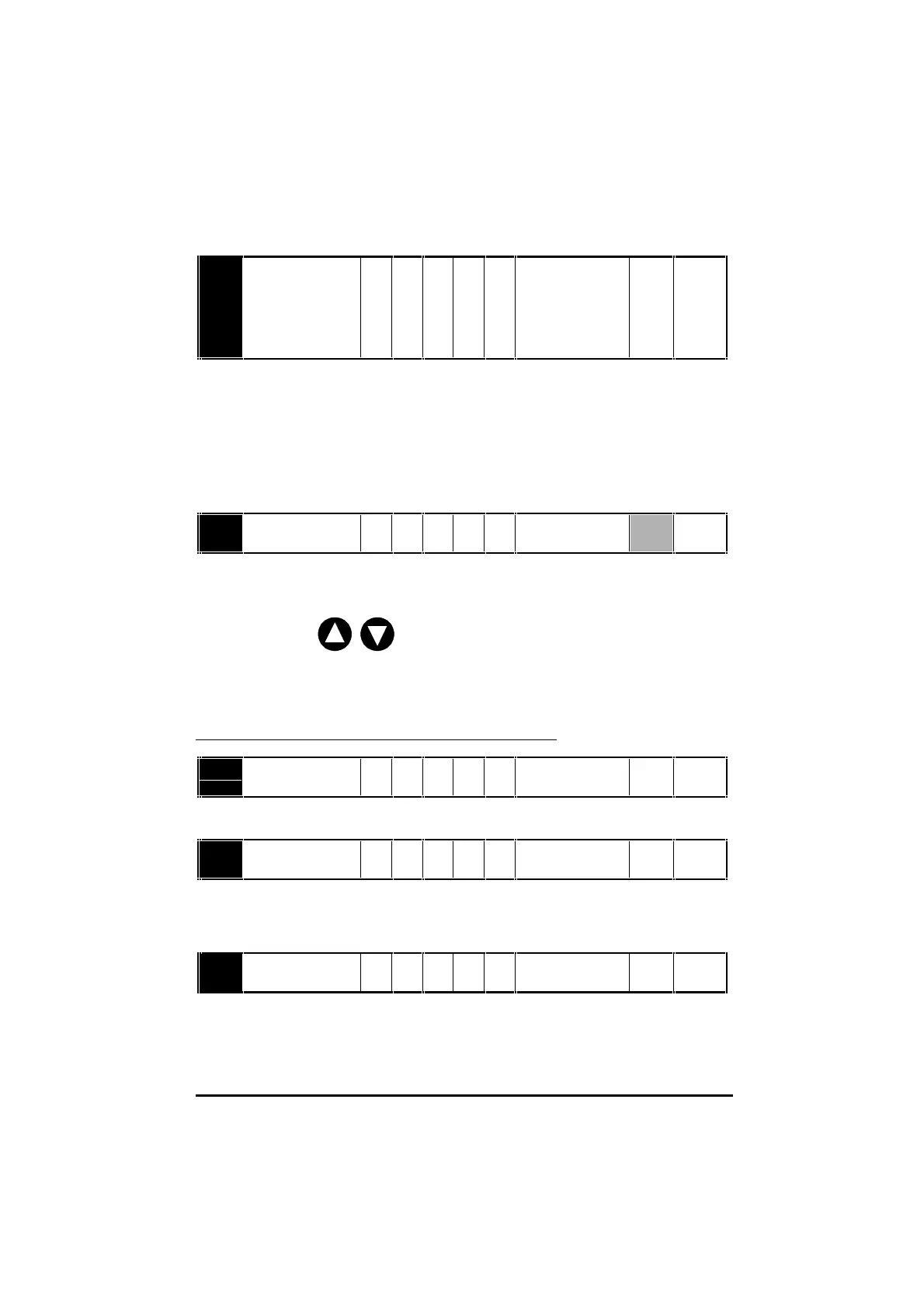
0.25 Analog input 2
mode selector
RW Txt ANS (0)
0.20 (1)
20.0 (2)
4.20 (3)
20.4 (4)
th (5)
Select the function of analog input 2 (terminals C4 and C5) as follows:
ANS (0) RS485 serial communications
0.20 (1) Current signal 0 to 20mA
20.0 (2) Current signal 20mA to 0
4.20 (3) Current signal 4 to 20mA
20.4 (4) Current signal 20mA to 4
th (5) Motor thermistor
0.35 Keypad speed
reference
RO Bi ±[0.02] Hz
0.35 indicates the value of the speed reference when the Drive is operating
in Keypad mode. The reference is then controlled by the following control
keys (when the display is in Status mode):
The value is automatically saved when the Drive is powered-down. At the
next power-up, the Drive ramps up to the speed that applied before the
power-down.
Serial communications
0.36 Serial comms.
baud rate
RW Txt 4.8
9.6
kB
When serial communications are used, set 0.36 at the required baud rate.
0.37 Serial comms.
address
RW Uni 0.0 ~ 9.9 group.unit
When the Drive is to be controlled and monitored using serial
communications, the Drive must be given an address. If necessary, change
the value of 0.37 to the required address.
0.38 initial parameter
displayed selector
RW Uni 0 ~ 50
See Changing the initial parameter to be displayed in Chapter 5.