Dinverter
A
User Guide
Issue code: d2au9
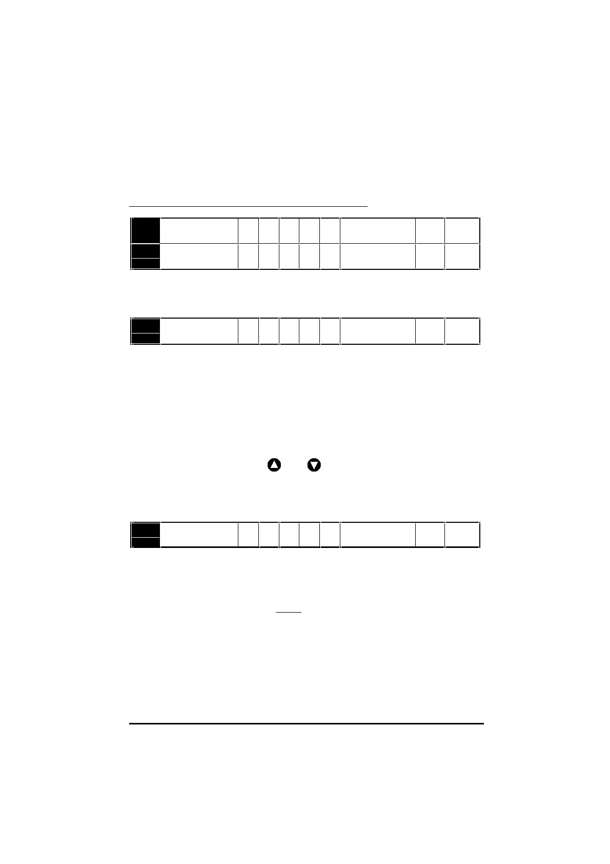
Ramps
Speed reference selection
Current limit
0.03 Acceleration rate RW Uni 0 ~ 999
seconds/100Hz
0.04 Deceleration rate RW Uni 0 ~ 999
seconds/100Hz
This acceleration and deceleration rate applies to both directions of
rotation. Note that the rates are related to frequency in Hz not speed in
RPM.
0.05 Speed reference
selector
RW P Uni 0 ~ 5
Set as follows to select the required source for the speed reference:
0 Analog input 1 (this setting is also used when control signal(s)
applied to digital input(s) are used to select the speed reference
source – see the Dinverter A Technical Reference Manual)
1 Analog input 1
2 Analog input 2
3 Preset speed reference
(see the Dinverter A Technical Reference Manual)
4 Keypad
and keys
5 Precision speed reference
(see the Dinverter A Technical Reference Manual)
The
LOCAL/REMOTE switch operates only when 0.05 is set at 0.
0.06 Current limit RW Uni
0 ~150 %(FLC ÷
[0.46])
Set 0.06 at the required value to limit the maximum output current of the
Drive to protect the Drive and/or motor from overload. The maximum
value depends on the values of FLC, 0.46 Motor rated current and
0.43 Motor power factor. Refer to Chapter 3 Data for values of FLC.
Current itlim
[. ]
[. ] [. ]==××××
006
100
046 043
Example
[0.06] = 150%, [0.46] = 4.3, [0.43] = 0.85
Current limit = 150% x 4.3 x 0.85 = 5.5A