Dinverter
A
User Guide
Issue code: d2au9
54
4.6 Bench-testing the Drive –
making temporary connections
0.5mm
(20AWG)
2
4 ×
1.0mm
(18AWG)
2
3 ×
2.5mm
(14AWG)
2
(Set parameter 0.05 at 4.)
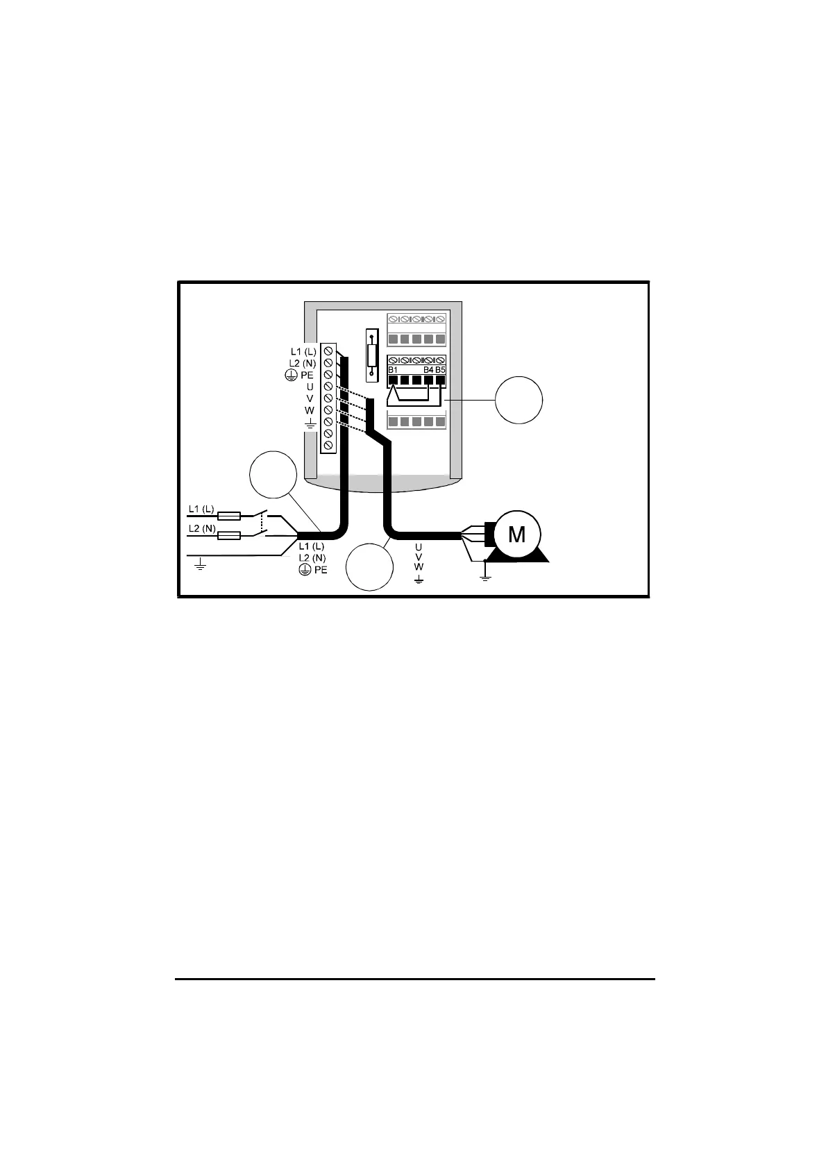
Figure 4–15 Temporary connections for bench-testing the Drive
in Keypad mode
The Drive can be operated in Keypad mode or Terminal mode when
bench-testing.
1 Observe the safety warnings and cautions given in this chapter and
refer to Working in the terminal chamber of the Drive earlier in this
chapter.
2 Make the signal and power connections for operation in Keypad or
Terminal mode as shown in Figure 4–15 or 4–16 as required. These
diagrams show optional connections to a motor. At this stage, do not
make these connections; you will be informed later when it will be safe
to do so.
It is not essential to connect a motor, but if a motor is to be
connected, the motor shaft must not be attached to any equipment,
or exposed. Note the Caution in Wiring recommendations earlier in
this chapter.
3 After the terminal cover is re-fitted, the Drive can be used. Refer to
Chapter 5 Programming instructions.