EVOLUTION COVER page-33
FIGURE 46: ESCAPE HATCH INSTALLATION
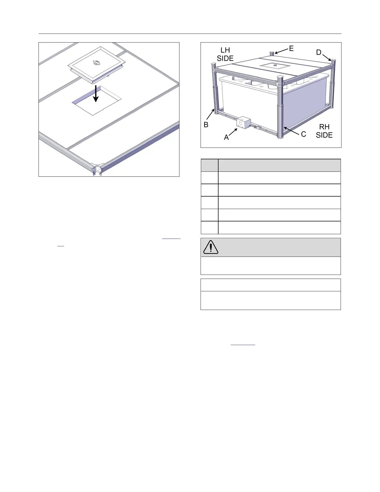
LIFTING MECHANISM INSTALLATION
1.
Install the motor frame in place, usually to the
opposite side of the spa entrance see Figure
47. The standard model will need the motor
frame to be on the short side of the cover,
whereas the long-side model will need the
motor frame on the long side of the cover.
FIGURE 47: OPERATOR AND JACKS INSTALLATION
ID DESCRIPTION
A OPERATOR
B MOTOR SIDE LEFT JACK
C MOTOR SIDE RIGHT JACK
D NON-MOTOR SIDE RIGHT JACK
E NON-MOTOR SIDE LEFT JACK
WARNING
Do not remove the alignment bracket on the top of
the jack (red part).
IMPORTANT NOTE
The next steps are side-specific. They are for the
non-motor left-hand side foot assembly.
2.
Install a foot bracket to the non-motor side
jack. Make sure to align the foot bracket on
the right side of the U-frame shaft as shown
see Figure 48.
240799 OWNER'S MANUAL REVISION 4