page-34 EVOLUTION COVER
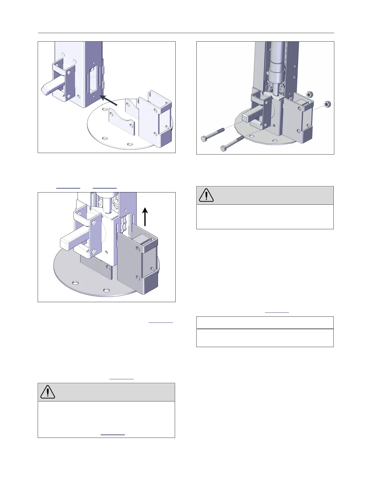
FIGURE 48: FOOT BRACKET INSTALLATION
3.
Slide the alignment vertical legs of the foot in
the bottom alignment slots of the jack see
Figure 48 and Figure 49.
FIGURE 49: INSERT LEGS IN SLOTS
4.
Push upwards to lock in place see Figure 49.
Make sure to get a full contact with the
bottom plate. Use a rubber mallet if
necessary.
5.
Install two 1/4″ x 2¼″ hexagonal head screws
and nylon- insert lock nuts. Use the
appropriate socket wrench spanner to fasten
the foot in place see Figure 50.
WARNING
To prevent the mechanism from bending inward, do
not overtighten the screws.
Make sure you respect the orientation of the
fasteners, as shown in Figure 50.
FIGURE 50: SCREW INSTALLATION
6.
Repeat previous steps with the non- motor
right-hand side foot.
CAUTION
Posts will fall easily when installed upright with the
foot installed. Secure the posts by laying them
down before proceeding with next step.
7.
Position the left non-motor-side jack in the
remaining corner of the cover. The square
shaft at the bottom of the jack should face
toward the motor frame, and the U- frame
bracket should be inwards. If not, review the
previous steps to install the left and right post
feet.
8.
Slide the drive shaft over the square shaft
located at the bottom of the left motor-side
jack assembly see Figure 51.
NOTE
The drive shafts are in the two long U-frames.
Remove the plastic film to locate them.
240799 OWNER'S MANUAL REVISION 4