EVOLUTION COVER page-35
FIGURE 51: DRIVE SHAFT INSTALLATION
9.
Hold the left- hand non- motor- side jack
assembly upright and in line with the left drive
shaft. Use a 3/4″ adjustable wrench to
carefully rotate the square shaft of the jack to
align with the drive shaft Figure 52.
CAUTION
Make sure the drive shaft is fully installed before
proceeding further in the installation process.
Using the jack without the drive shaft properly
connected may cause injury.
FIGURE 52: DRIVE SHAFT INSTALLATION
10.
Install the long aluminum U-frame over the
left drive shaft and make sure it lines up with
motor- side and non- motor- side jack
assemblies. Fasten in place using two
hexagonal 5/16″-18 x 2″ screws, two 5/16″-18
nylon-insert lock nuts and four 5/16″ plastic
washers (2 by side), with the 1/2″ (13 mm)
socket wrench and spanner as tools see
Figure 53.
NOTE
Do not fully tighten screws.
The drive shaft may fall off during operation, and
reassembling can be done faster when the bolts
have not been fully tightened see Figure 53.
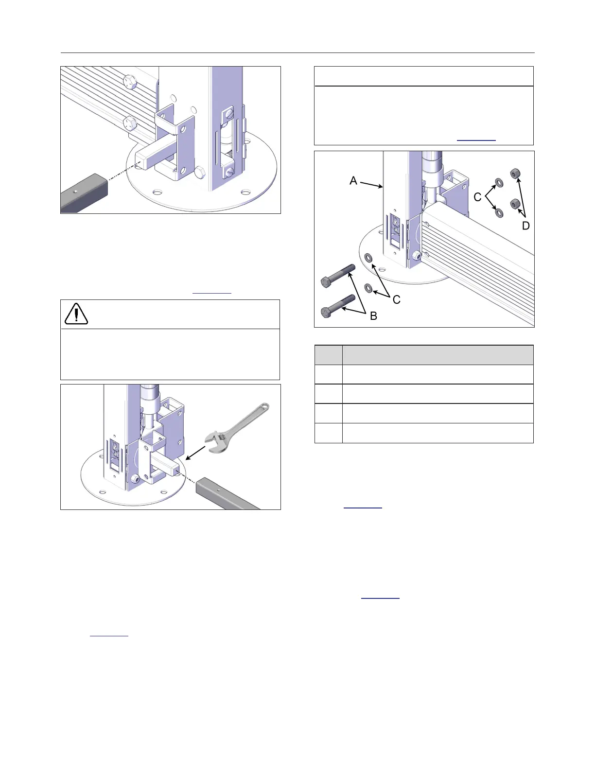
FIGURE 53: LONG U-FRAME INSTALLATION
ID DESCRIPTION
A NON-MOTOR SIDE JACK
B 5/16'' x 2'' HEX HEAD SCREWS
C PLASTIC WASHER
D NYLON INSERT LOCKNUT
11.
Repeat previous steps on the opposite side.
12.
Install one unpainted metal coupler on each
end of the spa entrance U- frame link see
Figure 54.
13.
Align one coupler with the holes on each end
of the spa entrance U-frame link. Use the
provided 1/4″ x 3/4″carriage bolts, 1/4″ nylon-
insert lock nuts and fasten the hardware with
the 7/16″ (11 mm) socket wrench and
spanner. There is one metal coupler per side
see Figure 54.
240799 OWNER'S MANUAL REVISION 4