page-36 EVOLUTION COVER
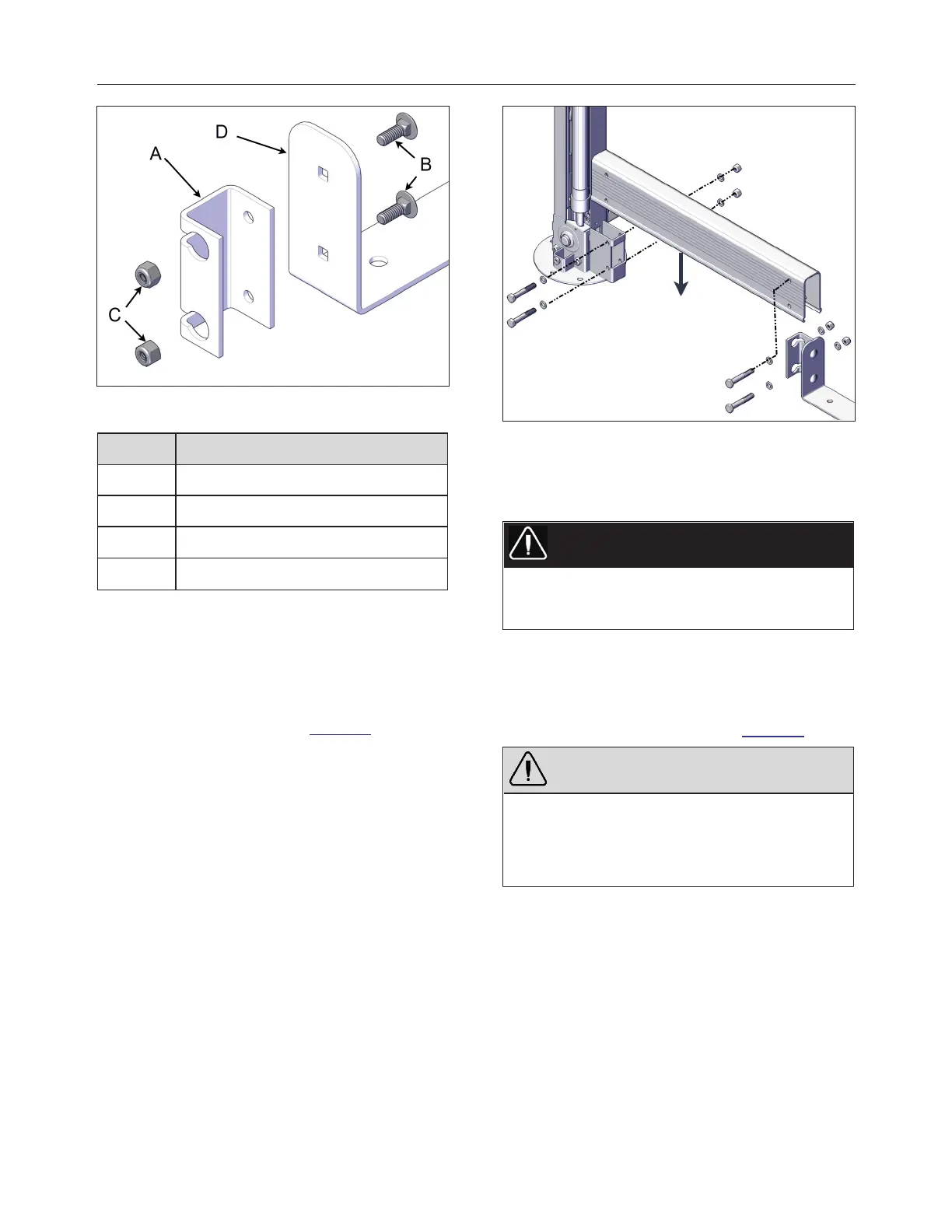
FIGURE 54: SAP ENTRANCE U-FRAME LINK AND METAL
COUPLER
ID DESCRIPTION
A UNPAINTED METAL COUPLER
B 1/4″ x 3/4″ CARRIAGE BOLT
C
1/4″ NYLON INSERT LOCK NUT
D SPA ENTRANCE U-FRAME LINK
14.
Fasten a short U-frame to each end of the spa
entrance U- frame link and then install the
entire assembly between the front posts. Use
four hexagonal 5/16″-18 x 2″ bolts, four 5/16″-
18 nylon- insert lock nuts and eight 5/16″
washers(4 by side). Use 1/2″ (13 mm) socket
wrench and spanner see Figure 55.
FIGURE 55: SHORT U-SHAPE INSTALLATION
15.
Check whether the drive shafts fell off during
installation. If so, review the previous steps.
If not, tighten all U-frame screws.
DANGER
Failure to verify the proper installation of the drive
shafts could result in the non-motor-side jacks
extending on their own.
16.
Once all the drive shafts are installed, the
jack lock screws located at the top of the non-
motor- side jacks can safely be removed.
Remove the Allen M8 x 50 mm screws and
keep them for future use see Figure 56.
WARNING
Failure to remove the locking screws will damage
the lifting mechanism when operating.
Do not remove the alignment bracket on the top of
the jack.
240799 OWNER'S MANUAL REVISION 4