EVOLUTION COVER page-37
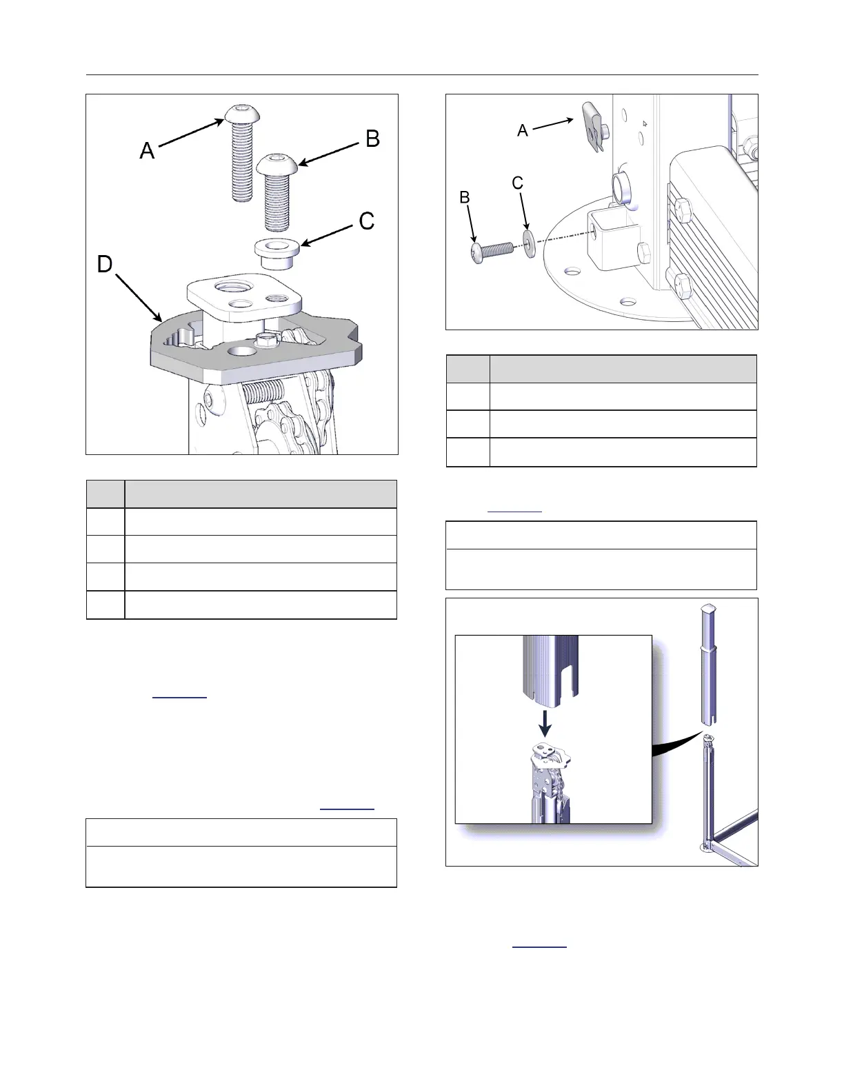
FIGURE 56: JACK LOCK SCREW
ID DESCRIPTION
A M8 x 50mm JACK LOCK SCREW
B 3/8″ x 1″ SOCKET HD SCREW
C BUSHING
D ALIGNMENT BRACKET (RED)
17.
Unscrew the 3/8″ x 1″ Allen bolt with a 7/32″
(5.5 mm) socket on the top of all four jack
assemblies. Put these parts in safe location
see Figure 56.
18.
Install the clip-on barrel nuts at the bottom of
the non-motor-side jack assemblies to hold
the sleeves in the bottom. Use Phillips M6 x
20 mm screws and 1/4″ nylon washers. Only
the non-motor-side jack assemblies need clip-
on barrel nuts to be installed see Figure 57.
NOTE
Do not fully screw in the M6 screws; a gap is
needed to slip on the sleeves.
FIGURE 57: CLIP-ON BARREL NUT INSTALLATION
ID DESCRIPTION
A CLIP-ON BARREL NUT
B M6 SCREW
C 1/4'' NYLON FLAT WASHER
19.
Slide the sleeves over all four jacks see
Figure 58.
NOTE
Be sure to align the cutouts at the bottom of the
sleeves with the U-frames.
FIGURE 58: SLEEVE INSTALLATION
20.
Fasten the sleeve with the Phillips M6 x 20
mm screws at the bottom of all four sleeves
see Figure 59.
240799 OWNER'S MANUAL REVISION 4