EasyManua.ls Logo

CPS ECB200KTL/US-800 - Page 116

Default Icon
135 pages
Print Icon
To Next Page IconTo Next Page
To Previous Page IconTo Previous Page
Loading...
Operation
115 / 135
EMS can connect many PCS and then PCS transfer information to BMS.
EMS
PCS BMS Batteries
PCS BMS Batteries
PCS BMS Batteries
. .
. . . . . . . . . . . . . .
. .
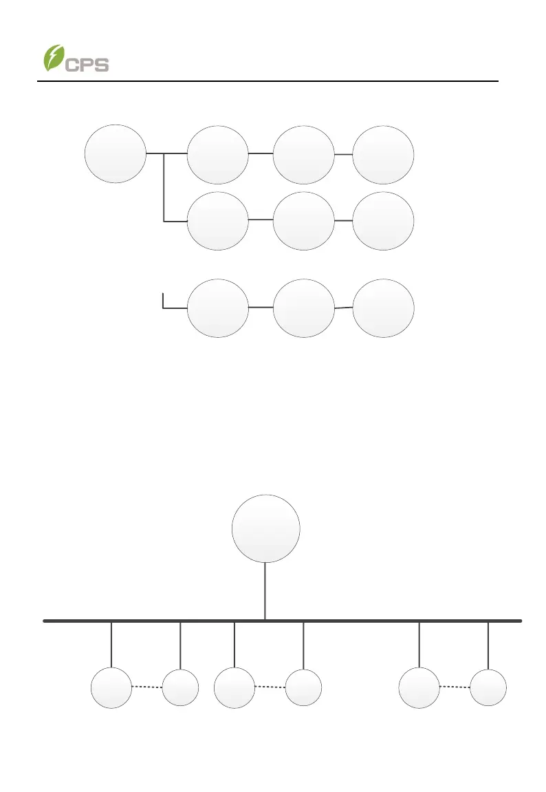
Figure 7-1b System connection (many PCS)
The EMS can also be directly connected to the BMS and the PCS respectively. All
the BMS and PCS can be daisy-chained and star-connected. The EMS manages the
two systems together. EMS can transfer information to BMS and the PCS
respectively, and BMS and the PCS can also transfer information to each other. The
communication is a triangular structure. Diagram 7-1c shows the system architecture.
EMS
RS485/CAN/ Ethernet
BMS1
PCS1
RS485/C
AN
BMS2
PCS2
. . . . . .
RS485/C
AN
RS485/C
AN
BMSn
PCSn
Figure 7-1c triangular structure diagram