CABRIOLE’
CRAMARO TS S.r.l. – 37044 COLOGNA V.TA (VR) - VIA QUARI DESTRA, 71/G TEL. +39 0442/411688 / FAX + 39 0442/411690
E-MAIL info@cramaro.com WEBSITE: http://www.cramaro.com - Manual n° MCA016-EN-ED00 – date 15/01/15
page 29
vc
CC
P
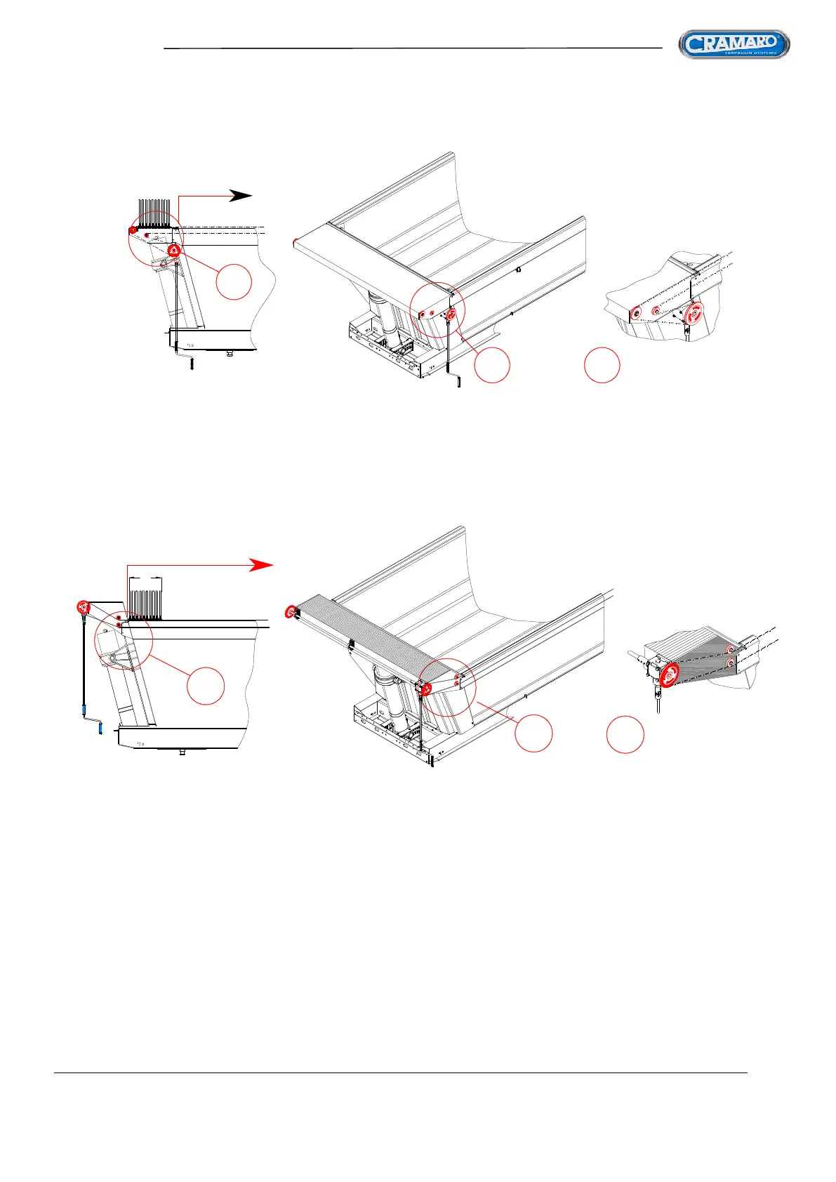
FIG 41
P
P
Option 2 - when the front unit clearance EXCEEDS 2040mm FROM THE CENTRE OF THE SLEWING
RING
vc
FIG 40
P P
P
2 - KEEP THE RAISED CAB-SHIELD and apply the pulling unit beneath the cab-shield itself (IF
POSSIBLE) and a series of pulleys on the sides of it to position the ropes that support the tarpaulin bows at the
proper height to allow them to slide.
The main defect of this system is that once the tarpaulin is retracted, it MUST occupy part of the vehicle
loading opening and can be damaged by the mechanical blade during loading.
Proper tarpaulin
assembly must be done following the operating instructions contained in this manual, following the procedure
requiring four successive working phases:
1. Assembling the entire mechanical part (manual, electric or hydraulic of the system)
2. Preparing, Positioning and assembling the tarpaulin sheet
3. Assembling the side and rear anchoring elastic cords
4. Adjusting, Calibrating and Finishing